Rotary device

a rotary device and axial direction technology, applied in the direction of bearings, rotary bearings, shafts and bearings, etc., can solve the problems of increasing the frequency of errors in reading/writing data, large displacement in the axial direction of the rotor, etc., to improve the stiffness of bearings, reduce the size, and prevent the effect of impact resistance degradation

Inactive Publication Date: 2011-08-18
SAMSUNG ELECTRO MECHANICS JAPAN ADVANCED TECHNOLOGY CO LTD
View PDF9 Cites 16 Cited by
  • Summary
  • Abstract
  • Description
  • Claims
  • Application Information

AI Technical Summary

Benefits of technology

[0006]There has been a demand for reducing the size in the axial direction of the rotary devices such as disk drive devices and improving the stiffness of bearings so as to prevent degradation in impact resistance. If the size in the axial direction of a rotary device such as a disk drive device is reduced, the distance between supporting points of a bearing in the radial direction of a bearing unit becomes shorter. Accordingly, the stiffness of the bearing of the bearing unit is lowered

Problems solved by technology

If the stiffness of the bearing of the bearing unit is lowered, this results in a larger displacement in the axial direction of a rotor including a recording disk when the rotary device such as a disk drive device is subjected to impact and vibr

Method used


Image

  • Rotary device
  • Rotary device
  • Rotary device

Examples


Embodiment Construction

[0016]Preferred embodiments of the present invention will be described below with reference to the accompanying drawings, in which like reference characters designate similar or identical parts throughout the several views thereof.

[0017]An embodiment according to an aspect of the invention will now be described with reference to the drawings. A hard disk drive (HDD) according to the embodiment is an example of a rotary device according to an aspect of the invention.

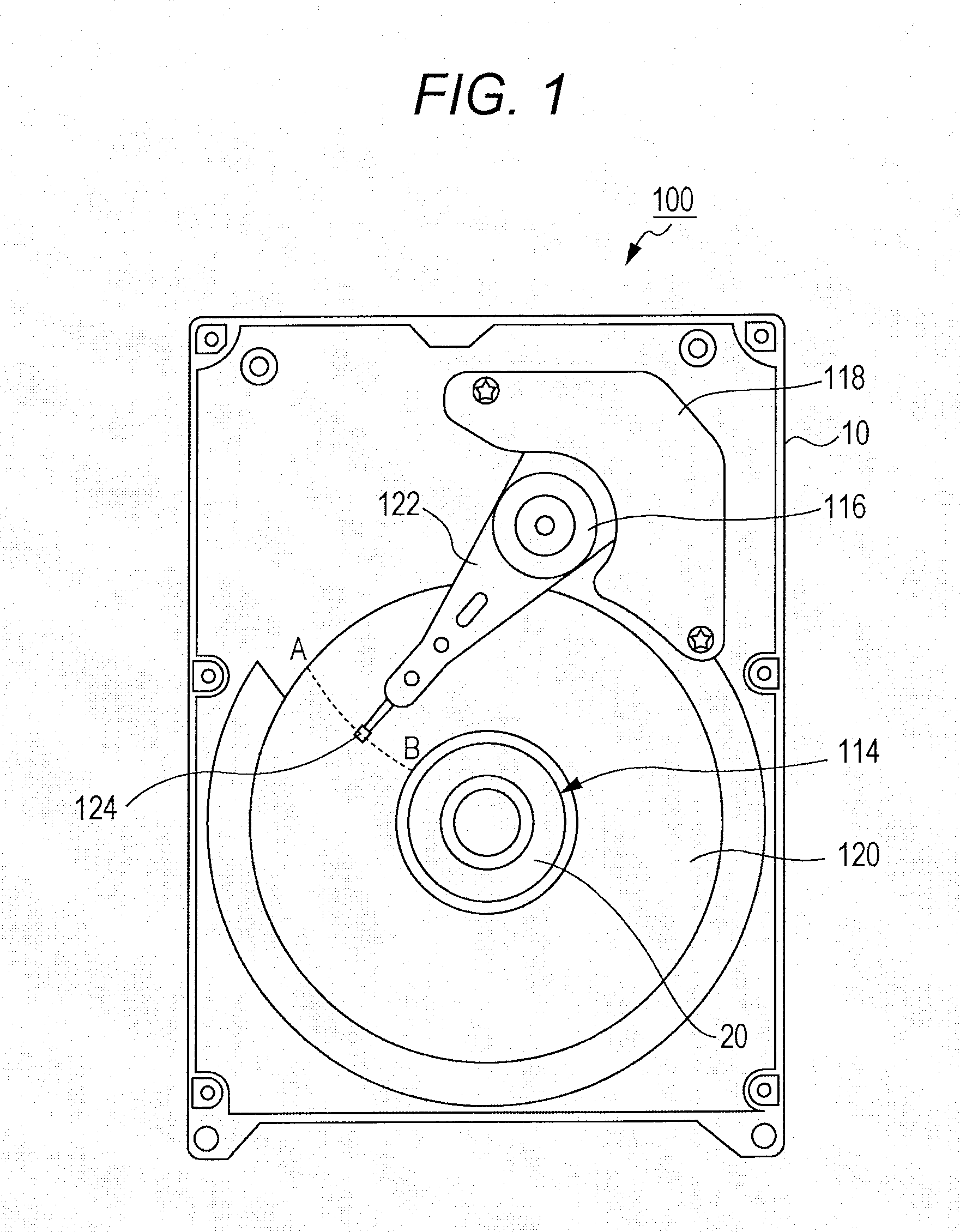
[0018]FIG. 1 is an explanatory view for explaining an internal structure of the HDD 100 (hereinafter referred to as a rotary device 100) according to the embodiment. FIG. 1 shows a state in which a cover is removed so as to expose the internal structure.

[0019]A brushless motor 114, an arm bearing unit 116, a voice coil motor 118 and the like are mounted on an upper surface of a base member 10. The brushless motor 114 supports, on a rotational axis, a hub 20 for mounting a recording disk 120 to rotationally drive the recor...


PUM


Abstract

A rotary device according to an aspect of the invention includes: a sleeve having an inner cylindrical surface, a first end portion and a second end portion at respective ends of the inner cylindrical surface; a shaft that is accommodated in the inner cylindrical surface in a manner rotatable relative to the inner cylindrical surface; a fluid present in a space between the shaft and the sleeve; a first pump portion formed in a middle portion of the inner cylindrical surface and configured to cause the fluid to flow toward the first end portion by the relative rotation of the shaft and the sleeve; a first radial narrow gap formed at a region of the inner cylindrical surface on a side of the first end portion with respect to the first pump portion; and a first circulation path communicated with the first pump portion.

Description

CROSS-REFERENCE TO RELATED APPLICATION[0001]This application is based on Japanese Patent Application No. 2010-029168 filed with the Japan Patent Office on Feb. 12, 2010, the entire content of which is hereby incorporated by reference.BACKGROUND[0002]1. Technical Field[0003]The invention relates to a rotary device such as a disk drive device, and more particularly, to a rotary device such as a disk drive device capable of maintaining the stiffness of a bearing even with a thinner structure.[0004]2. Related Art[0005]In recent years, some rotary devices such as disk drive devices as typified by hard disk drives (HDDs) have fluid dynamic bearing units mounted thereon. In such a fluid dynamic bearing unit, a space between a sleeve constituting a part of a stator and a shaft constituting a part of a rotor is filled with a lubricating fluid, for example. The fluid dynamic bearing unit supports the rotor in a non-contact state by dynamic pressure generated in a portion of the lubricating fl...

Claims


Application Information

Patent Timeline
IPC IPC(8): F16C32/06
CPCF16C17/107F16C33/107F16C2240/30F16C33/745F16C2370/12F16C33/1085F16C2210/04F16C2240/40
Inventor GOTO, HIROMITSU
Owner SAMSUNG ELECTRO MECHANICS JAPAN ADVANCED TECHNOLOGY CO LTD
Why Eureka
Try Eureka