Flexible stent having a pattern formed from a sheet of material

a flexible stent and pattern technology, applied in the field of balloon expandable stents, can solve the problems of stress points formed at each wire bend or turn, affecting the longitudinal stability of bent wire stents, so as to prevent longitudinal contraction or expansion of stents, minimize the thickness of stents, and prevent the effect of longitudinal expansion

Inactive Publication Date: 2011-03-22
COOK INC
View PDF72 Cites 16 Cited by
  • Summary
  • Abstract
  • Description
  • Claims
  • Application Information

AI Technical Summary

Benefits of technology

[0008]The foregoing problems are solved and a technical advance is achieved in an illustrative embodiment of a flexible stent comprising a waveform pattern that is formed from a sheet of malleable, biocompatible material having a specified uniform thickness. The pattern is formed into a tubular shape and into an overlapping state around a delivery catheter balloon for introduction through tortuous vessels to, for example, an occlusion site in a coronary vessel. To provide longitudinal flexibility while preventing longitudinal contraction or expansion of the stent during radial expansion of the stent, the pattern advantageously includes a reinforcing member extending longitudinally therealong. A plurality of cells extends laterally from the reinforcing member with selected of the closed cells each having a fixedly sized aperture therein. The c

Problems solved by technology

Although suitable for its intended use, a problem with these bent wire stents is that stress points are formed at each wire bend or turn.
As a result, the wire stent is structurally compromised at a number of points.
Furthermore, bent wire stents lack longitudinal stability.
A problem with this attempted remedy is that the cross-sectional dimension of the stent, or stent profile, is increased, and the stent intrudes into the effective lumen of the blood vessel.
As a result, the stent and tissue growth impede fluid flow and cause turbulence in the vessel lumen.
Another problem with this attempted remedy is that galvanic action, exposure to a reactive surface, or ion migration, occurs at the wire-to-wire contact points.
A problem with the use of a metal cannula stent is that the stent is rigid and inflexible.
As a result, the stent is difficult, if not impossible, to introduce through the tortuous vessels of the vascular system for deployment at a narrowed site.
Furthermore, the stent is too rigid to conform with a curvature of a blood vessel when deployed at an occlusion site.
Another problem with the use of a metal cannula stent is that the stent longitudinally shrinks during radial expansion.
A pro

Method used


Image

  • Flexible stent having a pattern formed from a sheet of material
  • Flexible stent having a pattern formed from a sheet of material
  • Flexible stent having a pattern formed from a sheet of material

Examples


Embodiment Construction

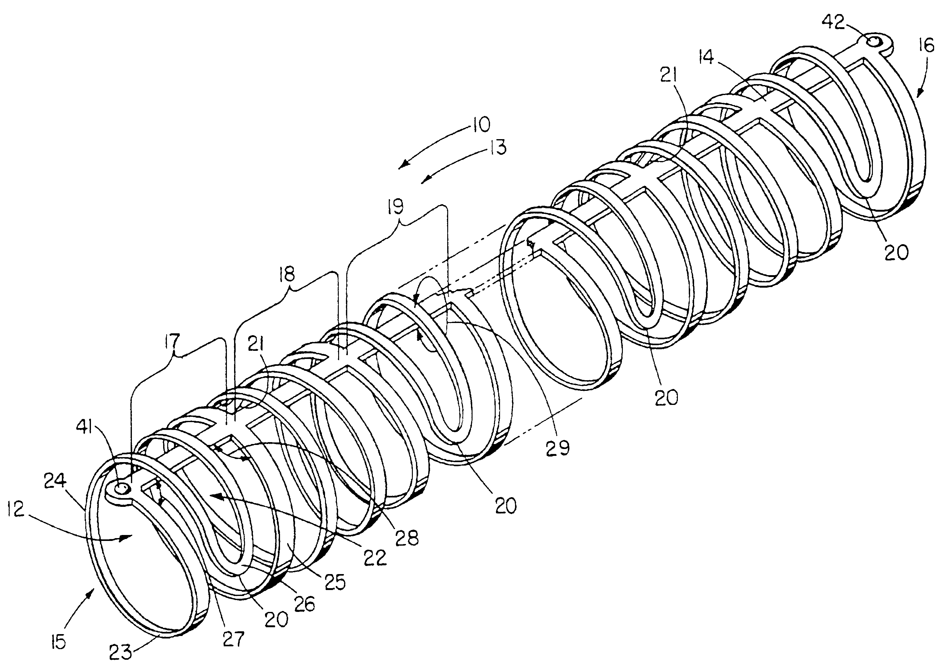
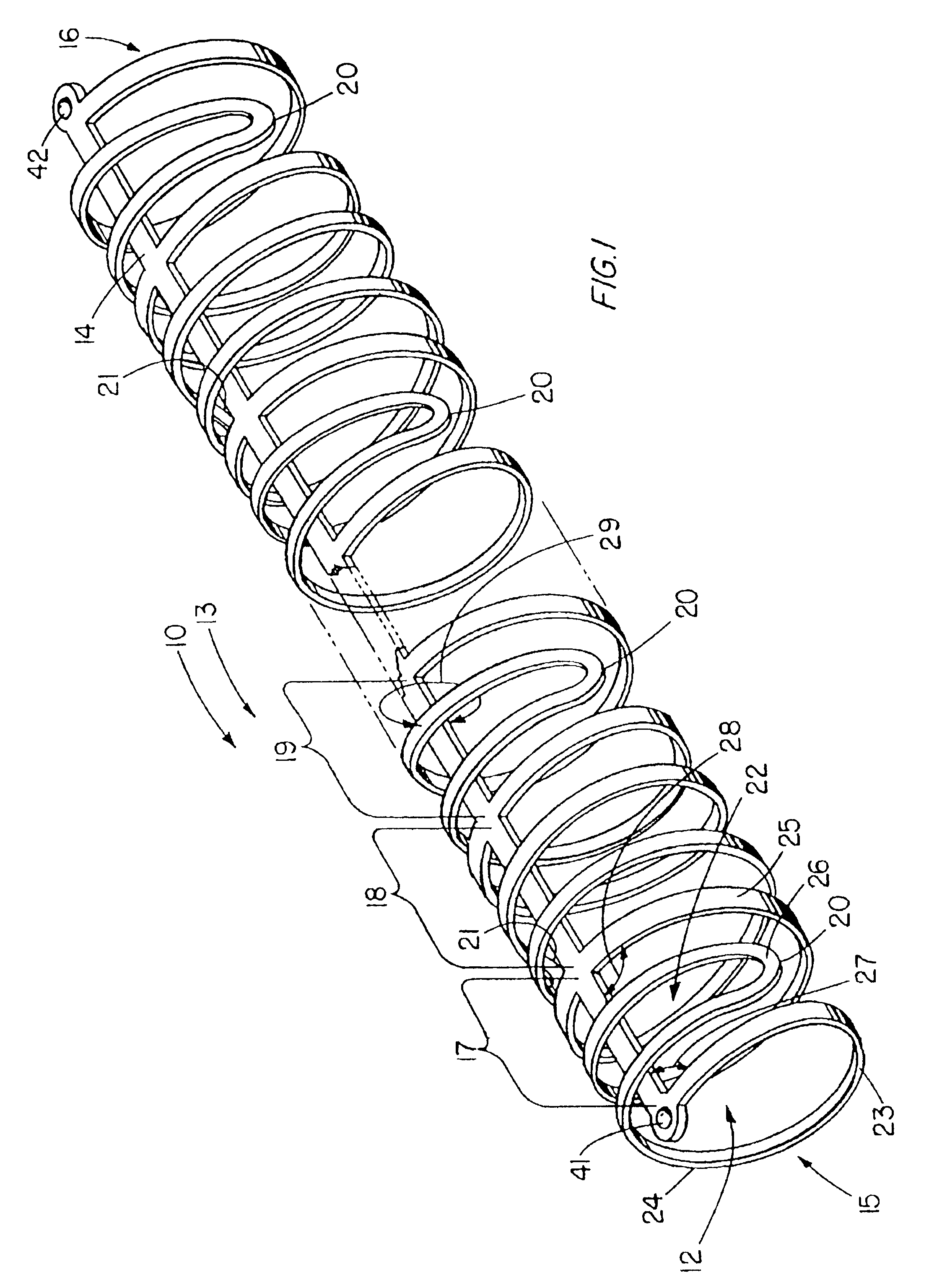
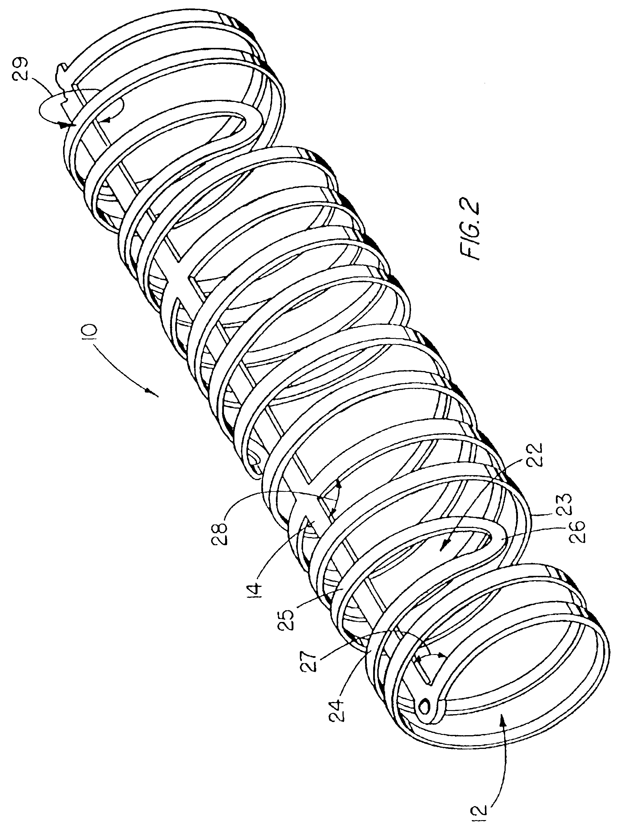
[0027]FIG. 1 depicts a pictorial view of a preferred illustrative embodiment of unmounted flexible stent 10 in an overlapping state and comprising a waveform pattern 13 formed from a flat sheet of biocompatible material and into a tubular shape 12. The tubular shaped pattern is expanded with a delivery catheter balloon in a body passage such as a blood vessel to maintain an open lumen therethrough. As depicted in FIG. 9, pattern 13 is formed from a flat sheet 11 of malleable, biocompatible material such as stainless steel by, for example, photochemically removing a majority of the sheet material and leaving a framework of integrated support members that has a small surface area relative to the initial surface area of the sheet. After formation from the sheet, the pattern is formed into a partially cylindrical or U-shaped surface around a cylindrical mandrel and then positioned in the overlapping state around a deflated, delivery catheter balloon and into tubular shape 12.

[0028]Patte...


PUM


Abstract

A flexible stent having a waveform pattern formed from a sheet of biocompatible material and into a tubular shape for maintaining the patency of a lumen such as in a coronary vessel. The waveform pattern of the stent is formed from a flat sheet of malleable, biocompatible material by, for example, photochemically etching the sheetbiocompatible material and leaving a framework or plurality of closed cells. The waveform pattern is formed into a tubular shape around a deflated, delivery catheter balloon with segments of the closed cells being interposed only overlapping a reinforcing member extending longitudinally along the stent. The stent material is treated to reduce the coefficient of friction of the material and to aid in the radial expansion of the stent with the balloon. Radiopaque markers are positioned at the ends of the stent to aid the physician in positioning the stent at an occlusion site.

Description

[0001]This is a reissue of application Ser. No. 08 / 748,669, now U.S. Pat. No. 6,409,752 B1, which is a continuation of Ser. No. 08 / 378,073 filed on Jan. 25, 1995 now U.S. Pat. No. 5,632,771 which is a file wrapper continuation of Ser. No. 08 / 097,392 filed on Jul. 23, 1993, now abandoned.TECHNICAL FIELD[0002]This invention relates generally to balloon expandable stents and, in particular, to a flexible stent having a waveform pattern formed from a sheet of biocompatible material and into a cylindrical surface or tubular shape. References herein to forming the stent from a “sheet” or “sheets” describe preferred embodiments of the invention, and are not to be construed to limit the claims. BACKGROUND OF THE INVENTION[0003]Vascular stents are deployed at a narrowed site in a blood vessel of a patient for widening the vessel lumen and circumferentially supporting the vessel wall. Vascular stents desirably present a small cross-sectional dimension or profile for introducing the stent in...

Claims


Application Information

Patent Timeline
IPC IPC(8): A61F2/06A61F2/00A61F2/88A61F2/92
CPCA61F2/885A61F2/92A61F2/958A61F2240/001A61F2250/0098
Inventor BOATMAN, SCOTT E.ROBERTS, KIMBERLY D.
Owner COOK INC
Why Eureka
Try Eureka