Bone fixation plate

a technology for fixing plates and bones, applied in bone drill guides, medical science, surgery, etc., can solve the problems of presenting the most challenges, and affecting the ability of bone and bony structures to provide support and structure, etc., and achieve the effect of increasing the magnitude of interferen

Active Publication Date: 2005-11-24
GLOBUS MEDICAL INC
View PDF11 Cites 111 Cited by
  • Summary
  • Abstract
  • Description
  • Claims
  • Application Information

AI Technical Summary

Benefits of technology

[0021] In another embodiment, the present invention comprises an apparatus for fixing a plate to bony material consisting essentially of at least one opening having a spherical curvature. At least one fastener having a head capable of engaging with and passing through an interference point of the spherical curvature is also included. In this embodiment, the fastener is prevented from backing out of the opening by the interference point. In this embodiment, the tangents to the spherical curvature intersect. As described above, another opening may be selectively positioned to increase the magnitude of interference at the interference point.

Problems solved by technology

Bones and bony structures are susceptible to a variety of weaknesses that can affect their ability to provide support and structure.
The cervical spine has presented the most challenges for doctors, partially due to the small size of the vertebrae and the spacing between adjacent vertebrae.
These devices caused many complications and involved significant risks.
In addition to the risks of surgically applying bone fixation plates, other complications arose.
Commonly, these problems involve loosening and failure of the hardware.
Two common failures are the breakage of the plates, and the backing out of the screws into soft tissues of the patient's body.
The backing out of the screws is typically a result of the screw's failure to achieve a sufficient purchase in the bone, although the stripping of the screws has also been known to cause this problem.
Regardless of the cause of the hardware failures, a surgeon must repair or replace the broken parts, which requires undesirable invasive procedures.
However, the backing out of screws remained a problem.
However, the shortened screw is typically unable to achieve a sufficient purchase in the bone.
Shortened screws often provide very little holding power and inadequate tactile feedback to the surgeon.
While the use of longer screws can provide bicortical fixation, this method also has its drawbacks.
Primarily, long screws increase the chances of interference with each other when they are screwed into bony tissue at an angle.
However, it is common for the bone grafts to experience compression, which separates at least one of the adjacent vertebrae from the bone graft.
Cervical plates that employ long screws do not allow for sufficient movement of the vertebrae to accommodate the compression of the bone graft, because the purchase of the screws is too great.
Thus, the vertebrae cannot move and are unable to adjusting to the compression of the bone graft.
However, this method of securing screws often becomes bulky, resulting in a large and undesirable profile.
For instance, the use of a c-ring that can expand as the fastener head is inserted requires additional components and assembly time to form a plate.
Moreover, multi-component designs may lose their ability to retain a fastener over time due to material failure, relaxation, or the like.
Additionally, multi-component configurations may not provide sufficient ability to lag the plate to the vertebral body.
One additional drawback of many designs is that they add to the overall height of the plate.
For example a plate design having a high overall height or a receptacle design that does not prevent screw backout may cause a patient to suffer from dysphasia.
Ultimately, the screw or plate may irritate or wear through neighboring tissue.
In addition, a high height plate or unretained loose screw in the lumbar spine may be abrasive to the aorta or vena cava.
Severe abrasion by the plate or screw in this instance may puncture the aorta or vena cava and cause internal bleeding.
In addition, many of these plates were not designed to allow for the locking of all of the screws, which left some of the screws susceptible to backout caused by tiny vibrations, or micromotion.
However, this led to the small parts falling off and getting lost.
In addition, the smaller parts are fragile and require special instruments in order to insert or manipulate them.
In addition, because of their small size, incorrect placement relative to the axis of the plate often causes sharp and jagged shavings to be formed as a locking screw contacts an improperly seated bone screw.
Prior attempts at increasing the screw purchase have resulted in risky procedures, or an insufficient ability to adapt to movement.
Attempts and decreasing the profile of bone fixation plates have resulted in lost parts, or insufficient purchase.

Method used


Image

  • Bone fixation plate
  • Bone fixation plate
  • Bone fixation plate

Examples


Embodiment Construction

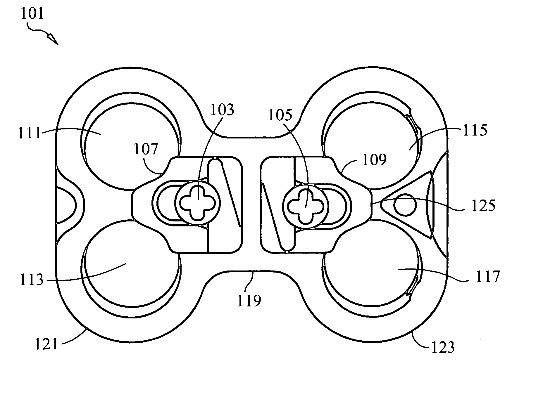
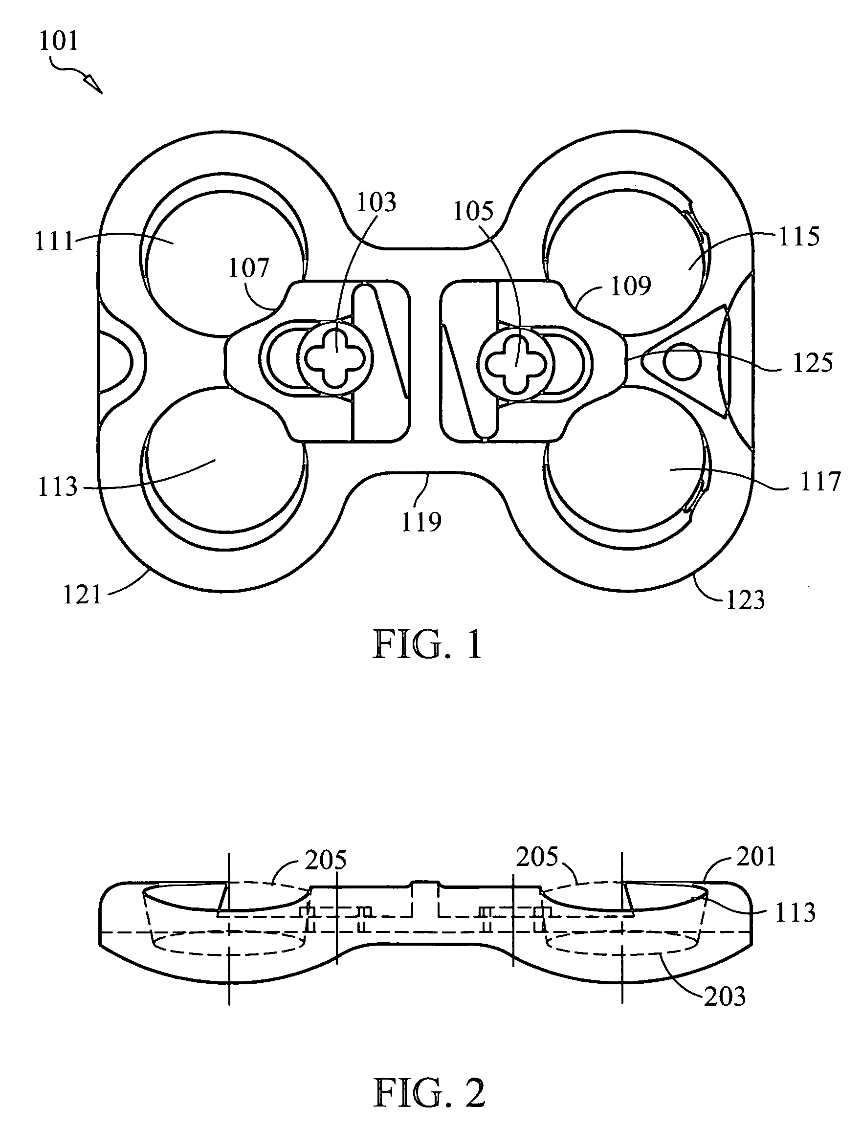
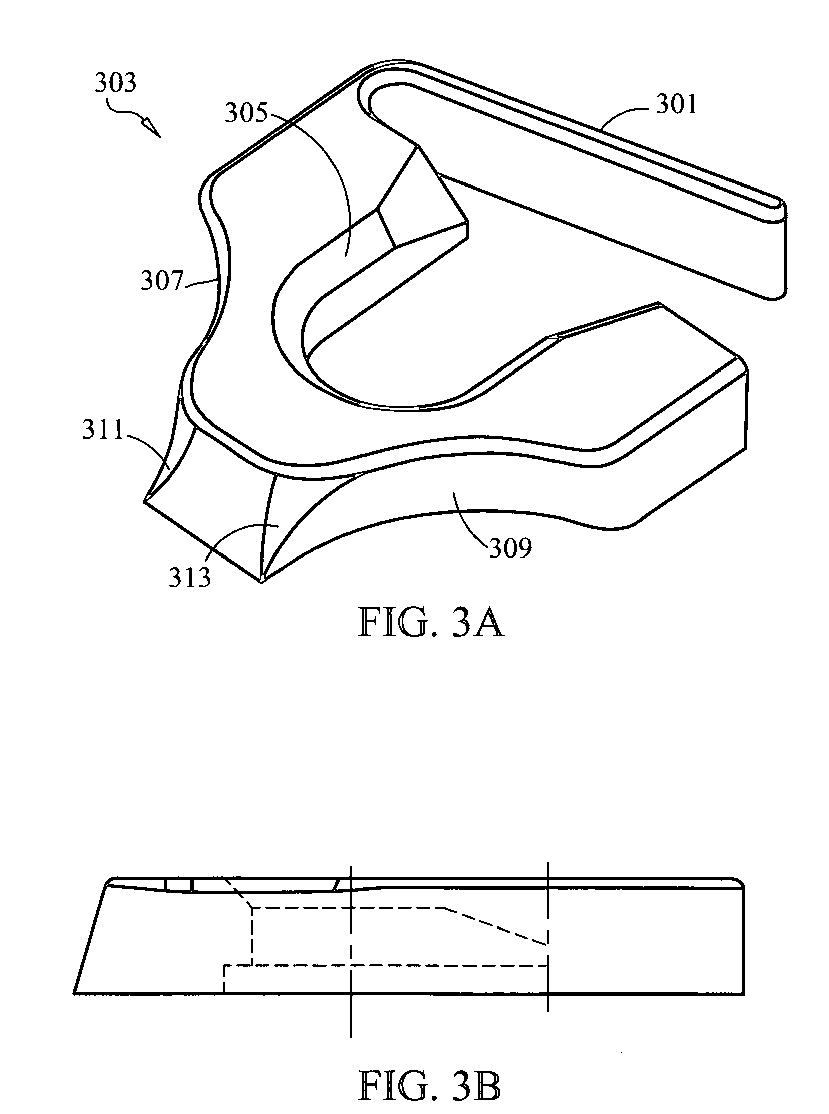
[0046] The present invention relates to a bone fixation plate that minimizes the problems associated with prior bone fixation plates while maintaining a small profile. In one embodiment, as a screw is tightened, it will begin to lag the plate to the bone. When the screw head interferes with the plate at an interference point, a slight resistance is generated. The insertion forces can easily overcome this resistance. When the screw is advanced further, it snaps into a sliding fit area and is allowed to move freely. The forces which can cause the screw to back out from the plate are preferably not strong enough to pass the screw head back past the interference section. It may be desirable to include a set screw to prevent backout of the screws due to micromotion. In other embodiments, the head of the screw may be clamped to prevent rotation, when such a restriction on the movement of the screw is desirable.

[0047] The present invention provides a locking mechanism that allows one or m...


PUM


Abstract

An apparatus for reducing the profile of a bone fixation plate while preventing backing out of screws is disclosed. The plate has at least two openings though which two screws can pass through bony tissue. The apparatus includes at least one section of relief and sections of engagement. As the screw is tightened, it will begin to lag the plate to the bone. When the screw head interferes with the plate at the interference point, there is a slight resistance that insertion forces can overcome. When the screw is advanced further, it snaps into the sliding fit area and is allowed to move freely. The forces that cause the screw to back out from the plate are preferably not strong enough to pass the screw head back past the interference section. At least one of the two openings is configured as an elongated slot to allow the screw to translate in the slot. It may be desirable to include a set screw to help prevent backout.

Description

CROSS-REFERENCE TO RELATED APPLICATIONS [0001] The present invention is a continuation-in-part application of co-pending U.S. patent application Ser. No. 10 / 826,285, the entire contents of which are incorporated by reference.FIELD OF THE INVENTION [0002] The present invention relates to a bone fixation plate used to stabilize vertebrae and other bony anatomy. More specifically, the present invention relates to a cervical plate having a minimized profile that easily and reliably prevents backout of fastening devices. BACKGROUND OF THE INVENTION [0003] Bones and bony structures are susceptible to a variety of weaknesses that can affect their ability to provide support and structure. Weaknesses in bony structures may have many causes, including degenerative diseases, tumors, fractures, and dislocations. Advances in medicine and engineering have provided doctors with a plurality of devices and techniques for alleviating or curing these weaknesses. [0004] The cervical spine has presented...

Claims


Application Information

Patent Timeline
Patent Type & Authority Applications(United States)
IPC IPC(8): A61B17/17A61B17/56A61B17/58A61B17/80A61B17/86A61B17/88
CPCA61B17/1728A61B17/8033A61B17/8042A61B2017/8655A61B17/8605A61B17/8615A61B17/8047A61B17/7059A61B17/1757
Inventor BINDER, LAWRENCE J.HANSELL, MATTHEW
Owner GLOBUS MEDICAL INC
Why Eureka
Try Eureka