Apparatus and a method for regulating the flow rate of fuel to a turboshaft engine in acceleration or in deceleration

a technology of turboshaft engine and flow rate, which is applied in the direction of engine control, turbine/propulsion fuel control, engine control, etc., can solve the problems of deterioration of the engine's turbine, reducing the air flow rate, and the speed of the rotation of the rotor falling off quickly, so as to avoid the pumping or flameout of the engine and increase safety

Inactive Publication Date: 2005-12-01
EUROCOPTER
View PDF3 Cites 12 Cited by
  • Summary
  • Abstract
  • Description
  • Claims
  • Application Information

AI Technical Summary

Benefits of technology

[0019] Furthermore, the above-described apparatus makes it possible in theory to avoid pumping or flameout of the engine insofar as the fuel flow rate is properly controlled. Nevertheless, the optimum regulation relationships are determined by testing performed on an engine that is new. Unfortunately, with wear (transmission shaft brake, damaged compressor blades, . . . ), the performance of the engine becomes degraded and that can lead to pumping or to flameout.
[0020] To avoid flameout, the control means, e.g. a stepper motor, possesses a bottom limit, thereby guaranteeing at least some minimum flow rate of fuel to the engine. In addition, in order to increase safety, the fuel metering system also has a bottom limit.

Problems solved by technology

An increase in pitch leads to the speed of rotation of the rotor falling off quickly.
Pumping is a phenomenon that affects the compressors of turboshaft engines when the angle of incidence of a rotor blade or of a rectifier becomes locally too great, leading to aerodynamic separation (stalling) which considerably reduces the air flow rate.
A consequence of this phenomenon is overheating in the combustion chamber which can lead to deterioration of the turbine of the engine.
That apparatus gives satisfaction, but it is not sufficiently reliable on its own to guarantee safe flight.
Unfortunately, experience shows that the sensor for sensing the pressure P3 is particularly fragile and is at the root of many anomalies.

Method used


Image

  • Apparatus and a method for regulating the flow rate of fuel to a turboshaft engine in acceleration or in deceleration
  • Apparatus and a method for regulating the flow rate of fuel to a turboshaft engine in acceleration or in deceleration
  • Apparatus and a method for regulating the flow rate of fuel to a turboshaft engine in acceleration or in deceleration

Examples


first embodiment

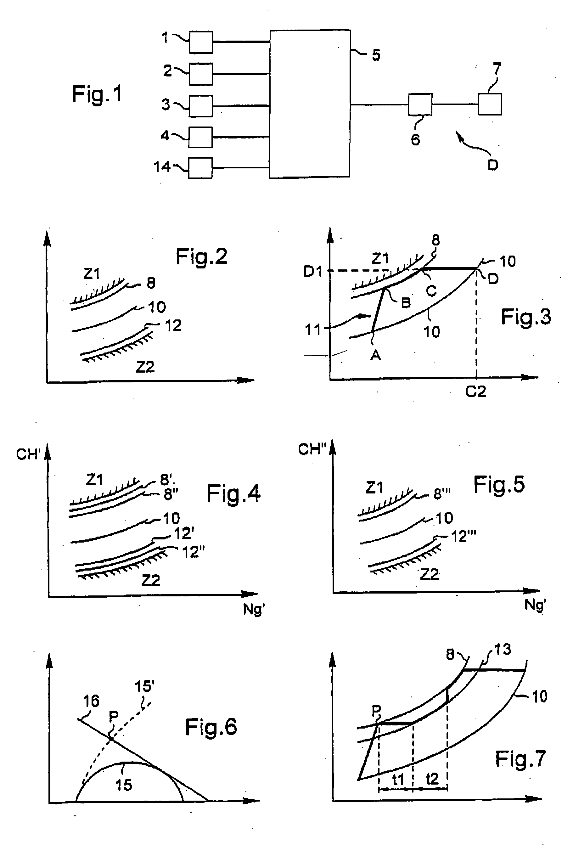
[0066]FIG. 4 is a graph showing the regulation relationships in a In this embodiment, the main modulated flow rate is equal to a primary modulated flow rate.

[0067] The primary modulated flow rate is obtained using the following first relationship in which CH′ represents the primary modulated flow rate, CH represents the fuel flow rate delivered to the engine, P0 represents external pressure, T0 represents external temperature, α represents a first power and β represents a second power: CH′=CH⁡(1013P0)α⁢(288T0)β

[0068] The first and second powers α and β depend exclusively on the type of engine. Experience shows that fuel flow rate regulation is optimized during acceleration with a first power α lying in the range 0.9 to 1.05, and a second power β lying in the range 0.6 to 0.9.

[0069] In addition, when the main modulated flow rate is equal to said primary modulated flow rate, there exist a plurality of optimum regulation relationships in acceleration, depending on altitude, e.g. a h...

second embodiment

[0070] In contrast, in a second embodiment, described with reference to FIG. 5, when the main modulated flow rate is equal to a secondary modulated flow rate, single optimum regulation relationships 8′″ and 12′″ are obtained respectively in acceleration or in deceleration and that are valid regardless of altitude.

[0071] Under such conditions, the secondary modulated flow rate is obtained using the following second relationship in which CH″ represents the secondary modulated flow rate, CH′ the primary modulated flow rate, and T0 the external temperature: CH″=CH′⁡(288T0)

[0072] The apparatus described above provides good control over the fuel flow rate to a turboshaft engine. Nevertheless, the optimum regulation relationship(s) is / are established on the basis of tests performed on an engine in good condition. With wear, engine performance can become degraded, thereby changing the shapes of the shaded zones Z1 and Z2. As a result, it becomes possible for pumping or engine flameout to o...


PUM


Abstract

Apparatus for regulating the flow rate of fuel to a turboshaft engine in acceleration or deceleration, the engine having a free turbine and a core engine, the apparatus including sensors transmitting information to regulator elements, the information relating: to a first speed of rotation NTL of the free turbine; to a second speed of rotation Ng of the engine's gas generator; to an internal temperature T4 of the gas at the inlet to the free turbine; to the external pressure; and to the external temperature. The apparatus further includes control elements activated by the regulator to actuate a fuel metering system of the engine. The regulator evaluates the flow rate of fuel to be supplied to the engine in acceleration or deceleration on the basis of at least one optimum regulation relationship, which determines a main modulated flow rate as a function of a modulated speed of rotation.

Description

[0001] The present invention relates to apparatus and to a method of regulating the flow rate of fuel to a turboshaft engine of a rotorcraft enabling acceleration, or deceleration, or indeed acceleration and deceleration, of said engine to be well controlled. BACKGROUND OF THE INVENTION [0002] This type of turboshaft engine is fitted with a regulator system whose main function is to regulate the power delivered by the engine during flight by controlling the fuel flow rate. The speed of rotation of the main rotor for providing the rotorcraft with drive and lift is then maintained at a value that is substantially constant. [0003] A rotorcraft is controlled in particular by acting on the pitch of blades of said main rotor. An increase in pitch leads to the speed of rotation of the rotor falling off quickly. The engine must then accelerate quickly so as to compensate for this drop in speed in order to enable the rotorcraft to be maintained in flight. Similarly, when the blade pitch is r...

Claims


Application Information

Patent Timeline
Patent Type & Authority Applications(United States)
IPC IPC(8): F02C9/28
CPCF02C9/28F05D2270/62F05D2270/04F05D2270/309F05D2270/303F05D2270/304
Inventor CERTAIN, BERNARD
Owner EUROCOPTER
Why Eureka
Try Eureka