Method for controlling initiation of a detonator

a technology of explosive detonators and initiation methods, which is applied in the direction of impact fuzes, weapons, ammunition fuzes, etc., can solve the problems of less than complex task of specific positioning of sufficient explosives to achieve a successful blast, and inability to achieve optimal physical rock breakage performance, etc., to achieve the effect of being easily modified

Inactive Publication Date: 2005-12-01
ORICA EXPLOSIVES TECH PTY LTD
View PDF4 Cites 27 Cited by
  • Summary
  • Abstract
  • Description
  • Claims
  • Application Information

AI Technical Summary

Benefits of technology

[0018] By knowing the deviation in the position of the detonators in the actual blast hole pattern from the pre-determined planned blast hole pattern, and using this...

Problems solved by technology

The optimisation of an explosive blast involves trying to obtain certain physical results from the explosion at minimum cost of explosive, which is a significant expense in many mining operations.
The specific positioning of sufficient explosive to achieve a successful blast is a complex task.
Blasting at above or below the actual response time can result in a less than optimal physical rock breakage performance.
However during drilling of blast holes, complications can arise and a hole may not be able to be drilled in a pre-determined location because of varying ground conditions.
Production constraints mean that operators are under pressure to load, set and fire a blast as quickly as possibl...

Method used


Image

  • Method for controlling initiation of a detonator
  • Method for controlling initiation of a detonator

Examples


example

[0043] An example according to the present invention will now be described.

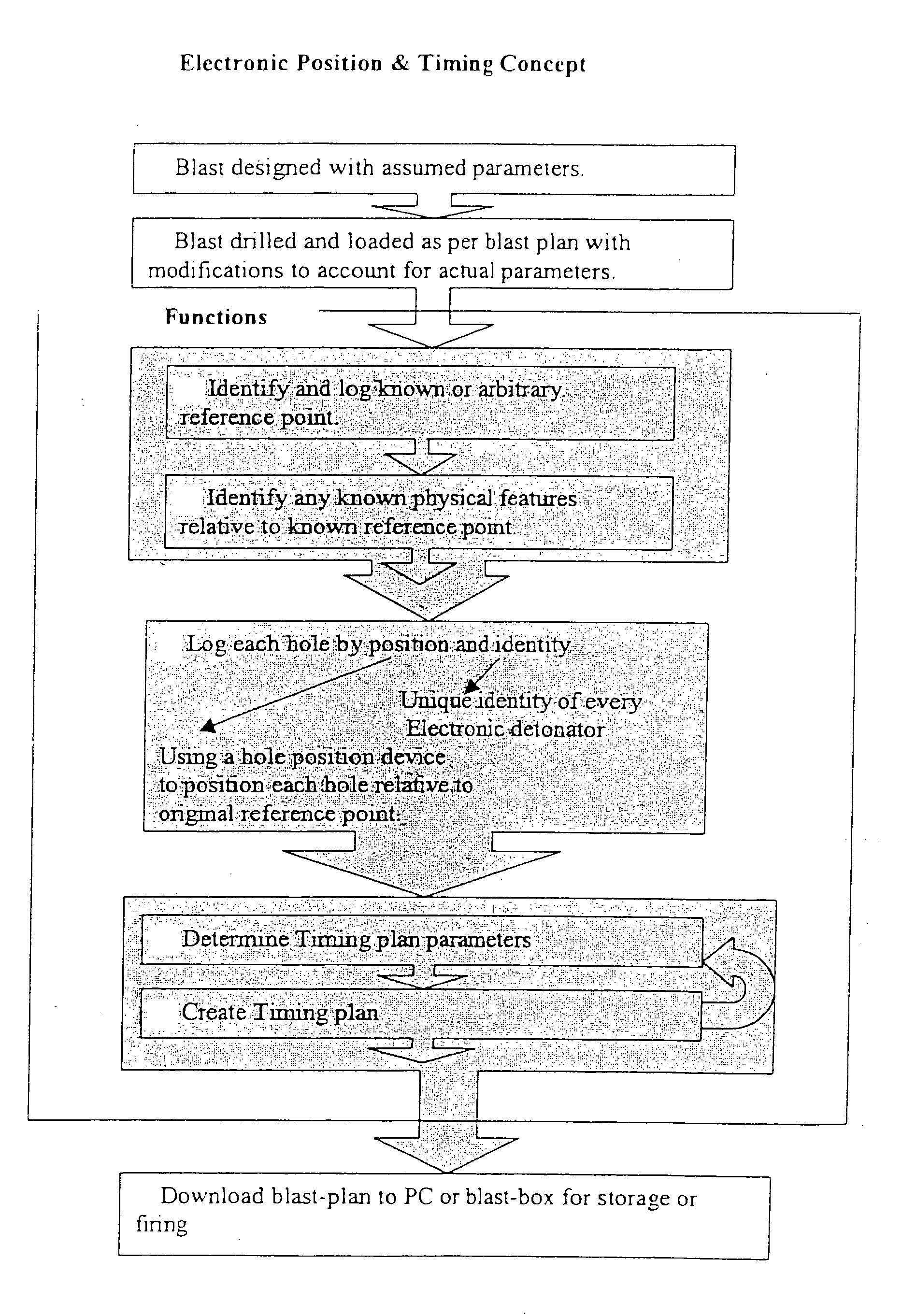
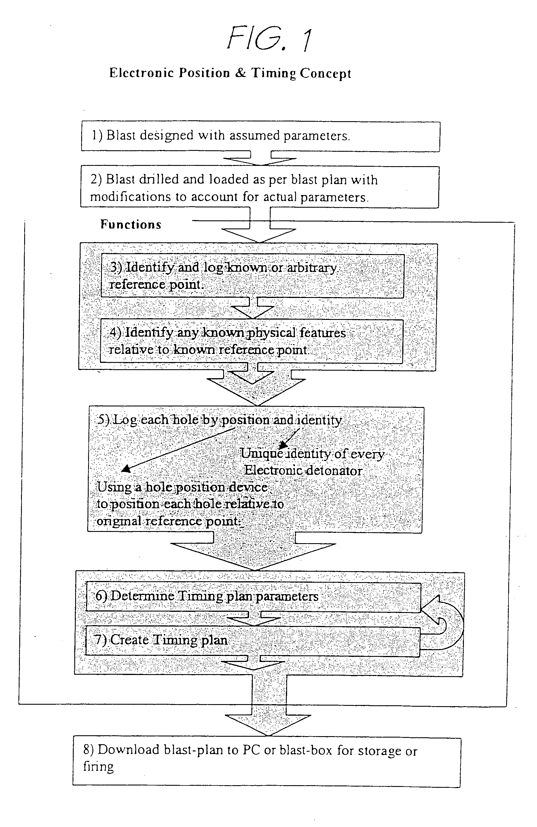
[0044] Referring to FIG. 1, in one form of the method of the present invention, there is no planned blast pattern provided and the time of initiation of an electronic detonator was controlled by a blast operator once the placement of the explosive and detonator in surrounding ground has occurred.

[0045] The blast operator measured the actual spatial position of the detonator(s) in relation to one or more adjacent detonators by first identifying and logging a known coordinate reference point, which can be one of a survey position, another blast hole or a physical feature such as the corner of the blast pattern area. Then the actual drilled blast hole spatial position was identified relative to that reference point. Each hole was also identified by a unique identity code or name, and its position was entered or logged into a recordal system. The order of identification of the blast holes in a blast pattern was...


PUM


Abstract

A method for controlling the initiation of an electronic detonator when located in surrounding ground, the method comprising the steps of: measuring the actual spatial position of the said detonator in relation to one or more adjacent detonators; and calculating the time of initiation of the said detonator based upon its actual spatial position.

Description

FIELD OF THE INVENTION [0001] The present invention relates to the control of explosive detonators. In particular the invention relates to controlling the initiation of an electronic detonator for use in a mining process, and will primarily be described with reference to this context. BACKGROUND ART [0002] In mining processes an explosive blast is conducted to fracture an orebody to enable recovery of the broken rock to obtain its associated minerals. Explosive material and a detonator for initiating the explosion are placed into a series of pre-drilled narrow elongate holes (blast holes) in the orebody, the area is cleared of people and equipment, and an explosion is set off. [0003] The optimisation of an explosive blast involves trying to obtain certain physical results from the explosion at minimum cost of explosive, which is a significant expense in many mining operations. The specific positioning of sufficient explosive to achieve a successful blast is a complex task. This task...

Claims


Application Information

Patent Timeline
IPC IPC(8): F42C1/00F42D1/055F42D3/04
CPCF42D3/04
Inventor JOHNSTON, PETERRUSSELL, JOHN KEIR
Owner ORICA EXPLOSIVES TECH PTY LTD
Why Eureka
Try Eureka