Scan converter

a technology of converter and scanner, applied in the field of scanner, can solve problems such as cost increas

Inactive Publication Date: 2005-12-01
MATSUSHITA ELECTRIC WORKS LTD
View PDF21 Cites 52 Cited by
  • Summary
  • Abstract
  • Description
  • Claims
  • Application Information

AI Technical Summary

Benefits of technology

[0006] In view of the above problem, the object of the present invention is to provide a scan converter which can stably convert progressive scan video data into inte

Problems solved by technology

Still furthermore, because the scan converter ne

Method used


Image

  • Scan converter
  • Scan converter
  • Scan converter

Examples


first embodiment

(First Embodiment)

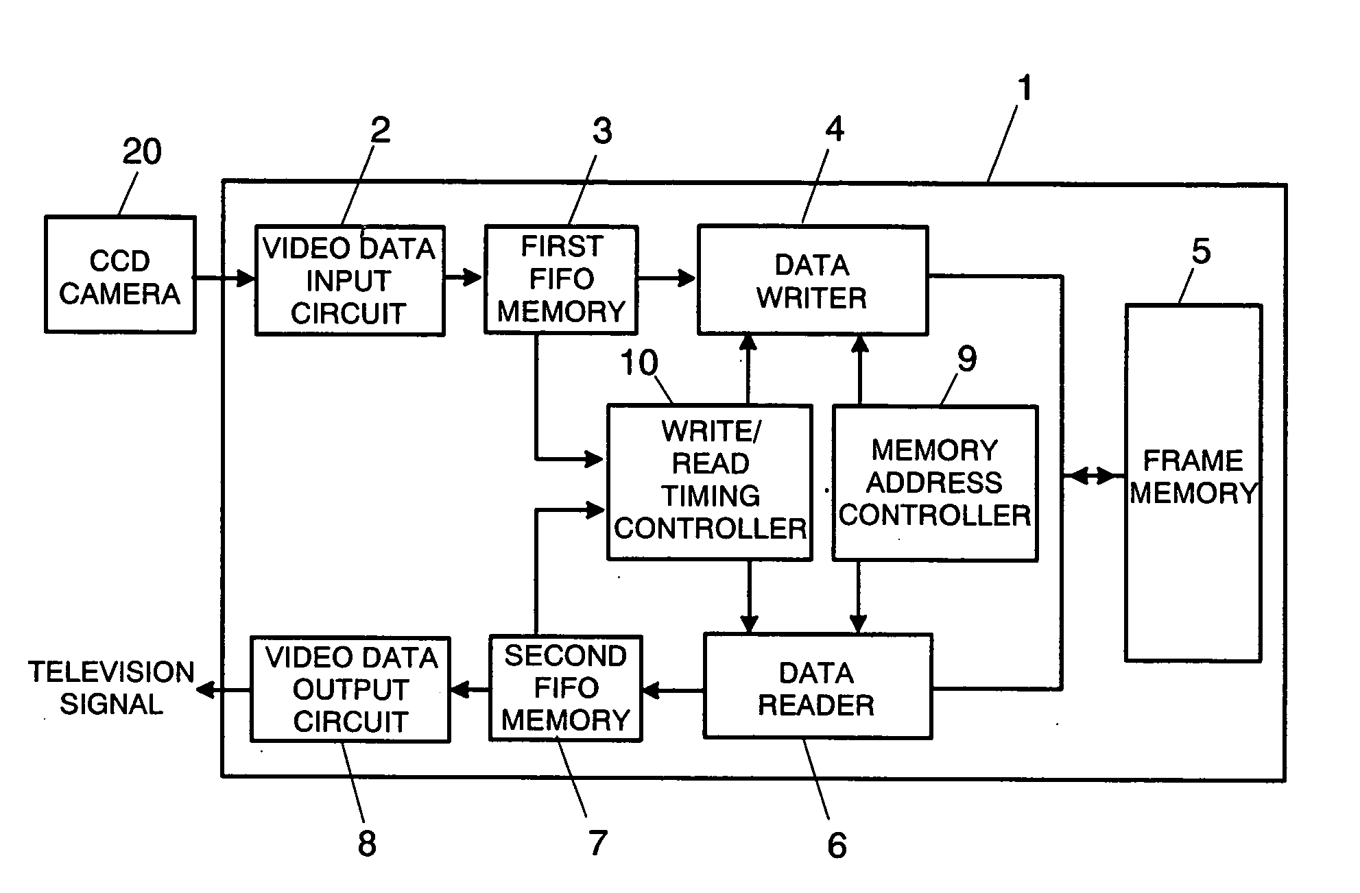
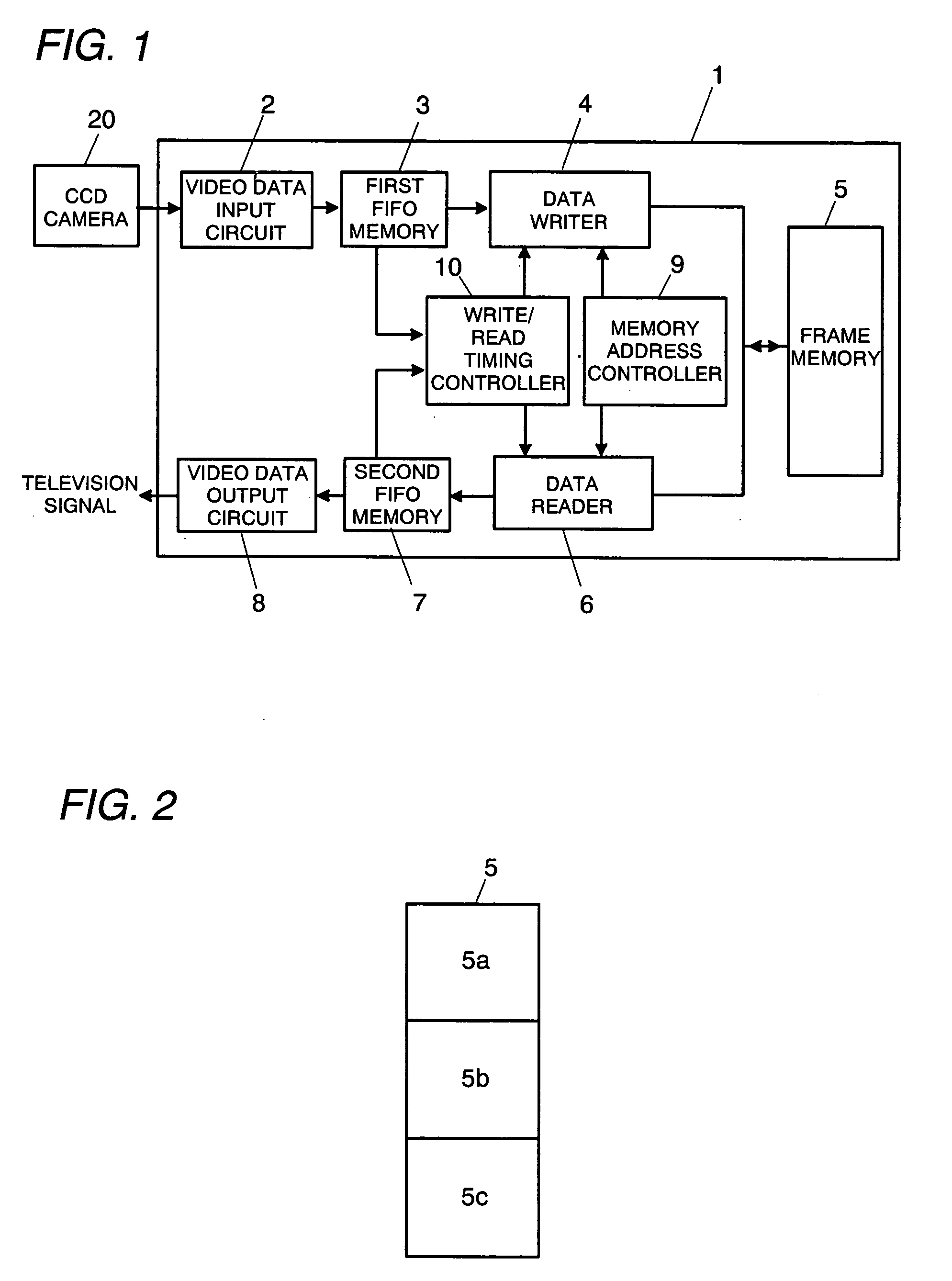
[0027]FIG. 1 is a block diagram of a scan converter in accordance with a first embodiment of the present invention. The scan converter 1 takes a progressive scan video data from a CCD camera 20 and outputs an interlaced scan video data based on the standard television signal (NTSC, PAL, or SECAM). The CCD camera 20 outputs video data in progressive scan mode at a first transfer rate which is determined by a clock signal supplied to the CCD camera 20 or a signal obtained by dividing the clock signal. In this embodiment, the first transfer rate is faster than a transfer rate (a third transfer rate) which is based on the standard television signal.

[0028] The scan converter 1 comprises a video data input circuit 2, a first FIFO memory 3, a data writer 4, a frame memory 5, a data reader 6, a second FIFO memory 7, a video data output circuit 8, a memory address controller 9, and a write / read timing controller 10.

[0029] The video data input circuit 2 takes the video dat...

second embodiment

(Second Embodiment)

[0065]FIG. 9 shows a scan converter 100 in accordance with a second embodiment of the present invention. The basic composition of this embodiment is identical to the first embodiment, so the similar part of these embodiments are identified by the same reference character and no duplicate explanation is made here. In this embodiment, too, the first transfer rate is faster than the third transfer rate.

[0066] This scan converter 100 includes an arithmetic processing circuit 11 which performs computations, such as resizing, filtering, and zooming of an image, in addition to the composition of the first embodiment.

[0067] The second FIFO memory 7 in this embodiment has a data storage capacity of 24 words, and when it has available space of 16 or more words, it outputs a read request signal to the write / read timing controller 10.

[0068] As shown in FIG. 10, the write enable signal is held high during a period needed for transmitting 8 words from the first FIFO memory 3...


PUM


Abstract

The scan converter comprises first and second memories 3, 7, a frame. memory 5 having a write period and a read period, a video data input circuit 2 for writing data at a first transfer rate into the memory 3, a video data output circuit 8 for outputting the data from the memory 7 at a third transfer rate. The transfer rate between the memories 3, 7 and the memory 5 is twice as fast as the first or third transfer rate, whichever is faster, and the memories 3 has data storage capacities greater than an amount of the data to be written into the memory 5 in each write period, and the memories 7 has data storage capacities greater than an amount of the data to be read from the memory 5 in each read period.

Description

TECHNICAL FIELD [0001] The present invention relates to a scan converter, more particularly, to a scan converter for converting progressive scan video data into interlaced scan video data. BACKGROUND ART [0002] Japanese Patent Publication No. 3363761 discloses a scan converter for converting progressive scan video data into interlaced scan video data. The scan converter comprises a frame memory and line memories, and one line of progressive scan video data sent from an image pickup means is written into the line memory at normal transfer rate in a certain period. In the next period, the video data written into the line memory is read out therefrom and written into the frame memory at twice the normal transfer rate in the first half of the period, while another line of the progressive scanning video data is written into the above line memory at the normal transfer rate, and, in the latter half of the period, the video data stored in the frame memory is read out therefrom at twice the...

Claims


Application Information

Patent Timeline
IPC IPC(8): H04N11/20H04N7/01
CPCH04N7/012
Inventor ENDO, JUNPEIFURUKAWA, SATOSHIHAGIO, KENICHI
Owner MATSUSHITA ELECTRIC WORKS LTD
Why Eureka
Try Eureka