Image display device, image display method, and television receiver

a technology of image display and display method, which is applied in the direction of selective content distribution, television systems, instruments, etc., can solve the problems of user fatigue, screen luminance becomes too high, screen brightness becomes too bright, etc., and achieves the effect of screen luminance and lower luminan

Inactive Publication Date: 2005-12-01
SHARP KK
View PDF7 Cites 106 Cited by
  • Summary
  • Abstract
  • Description
  • Claims
  • Application Information

AI Technical Summary

Benefits of technology

[0029] It is an object of the present invention to provide an image display device that consumes less power and displays a television video and a graphic user interface (GUI) video in an easy-to-see manner by controlling the screen thereof to an appropriate luminance level in response to display mode switching.
[0030] It is another object of the present invention to provide an image display device that consumes less power and displays a television video and a computer video in an easy-to-see manner by appropriately controlling luminance intensity of a backlight source thereof in response to display mode switching.
[0031] It is yet another object of the present invention to provide an image display device that consumes less power and displays a television video and a video of screen for inputting character in an easy-to-see manner by controlling the screen thereof to an appropriate luminance level in response to display mode switching.

Problems solved by technology

Thus, if a graphic user interface (GUI) video, which is rather closer to a computer video such as an electronic program guide and a variety of setting menus, is displayed on the television receiver with a high luminance level set for television video displaying, the screen luminance becomes too high and the screen becomes too bright.
A long time of viewing such a screen leads to eye fatigue of the user.
A major portion of power consumption of a large liquid crystal display device is attributed to a backlight unit thereof.
A long time of viewing such a screen leads to eye fatigue of the user.
However, the digital broadcast receiver doesn't take into consideration the screen luminance of a video display displaying received video data so that the user eye fatigue and power consumption are not reduced.

Method used


Image

  • Image display device, image display method, and television receiver
  • Image display device, image display method, and television receiver
  • Image display device, image display method, and television receiver

Examples


first embodiment

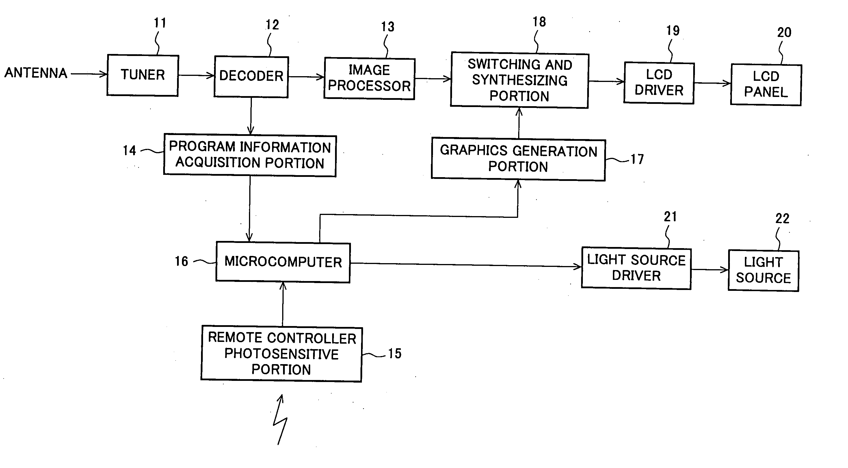
[0099] A liquid crystal display (LCD) television receiver as an image display device of a first embodiment of the present invention is described below with reference to FIGS. 6 through 14. FIG. 6 is a block diagram illustrating a schematic structure of the LCD television receiver of the first embodiment. FIG. 7 is an external view of a remote controller of the LCD television receiver of the first embodiment. FIG. 8 illustrates a display example of an EPG (electronic program guide) display screen of the LCD television receiver in accordance with the first embodiment. FIG. 9 illustrates a display example of a program information display screen of the LCD television receiver in accordance with the first embodiment. FIGS. 10A and 10B illustrate display examples of a setting menu screen of the LCD television receiver in accordance with the first embodiment.

[0100]FIG. 11 is a flowchart illustrating control operation of the LCD television receiver in accordance with the first embodiment. ...

second embodiment

[0134] An LCD television receiver external connectable to a PC, as a second embodiment of the present invention, is described below with reference to FIGS. 15 through 22. FIG. 15 is a block diagram illustrating a schematic structure of the LCD television receiver in accordance with the second embodiment of the present invention. FIG. 16 is a flowchart illustrating the control operation of the LCD television receiver in accordance with the second embodiment. FIG. 17 illustrates an OSD display screen of an input switch setting menu of the LCD television receiver in accordance with the second embodiment.

[0135]FIG. 18 illustrates the control operation of the LCD television receiver of the second embodiment. FIG. 19 is a flowchart illustrating the control operation of the LCD television receiver of the second embodiment. FIG. 20 illustrates another control operation of the LCD-television receiver in accordance with the second embodiment. FIG. 21 illustrates a display screen example of a...

third embodiment

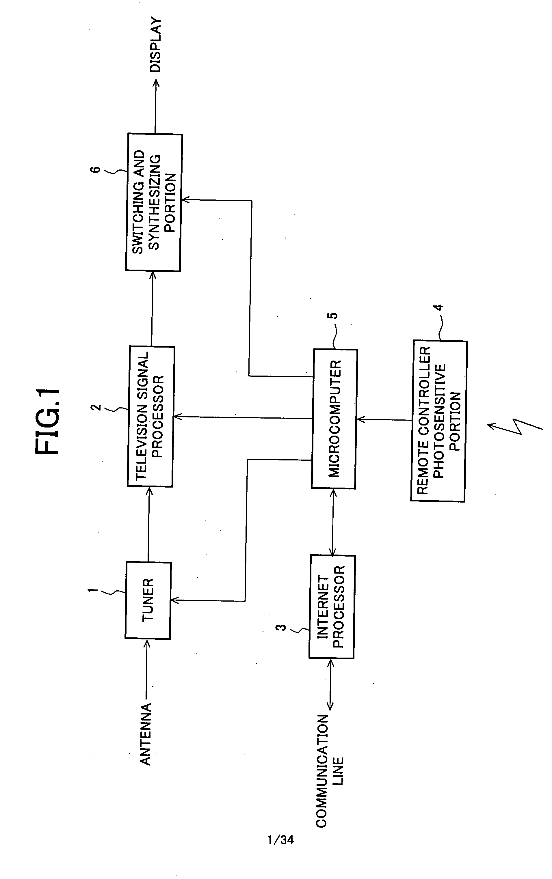
[0164] An LCD television receiver as an image display device in accordance with a third embodiment of the present invention is described below with reference to FIGS. 23-27. Like elements of the aforementioned FIG. 1 are designated like reference numerals, and the discussion thereof is omitted herein. FIG. 23 is a block diagram illustrating a schematic structure of the LCD television receiver of the third embodiment. FIG. 24 is a flowchart illustrating control operation of the LCD television receiver of the third embodiment. FIG. 25 illustrates the control operation of the LCD television receiver of the third embodiment. FIG. 26 is a flowchart illustrating the control operation of the LCD television receiver of the third embodiment. FIG. 27 illustrates another control operation of the LCD television receiver of the third embodiment.

[0165] As shown in FIG. 23, the LCD television receiver of the third embodiment comprises an LCD driver 7 for driving source lines and gate lines of an ...


PUM


Abstract

An image display device controls a screen luminance to an appropriate value in response to switching of a display mode, thereby displaying each of television broadcast program images and graphic user interface images (including an electronic program guide, and a variety of setting menus) in an easy-to-see and power-saving manner. The image display device switches between a mode of displaying the television image and a mode of displaying the graphic user interface image. In response to the mode switching instruction, the device controls variably luminance intensity of a backlight source, thereby providing a screen luminance appropriate for each mode.

Description

CROSS-NOTING PARAGRAPH [0001] This non-provisional application claims priority under 35 U.S.C. §119(a) on Patent Applications No. 2004-158517 filed in JAPAN on May 28, 2004, No. 2005-016218 filed in JAPAN on Jan. 25, 2005, No. 2005-027177 filed in JAPAN on Feb. 3, 2005, No. 2005-070439 filed in JAPAN on Mar. 14, 2005, and No. 2005-076171 filed in JAPAN on Mar. 17, 2005, the entire contents of which are hereby incorporated herein by reference. BACKGROUND OF THE INVENTION [0002] 1. Field of the Invention [0003] The present invention relates to an image display device and an image display method for displaying a selected video on a screen thereof by switching between a television program video screen and a graphic user interface video screen, between a television video signal and a computer video signal, or between a television program video screen and a screen for inputting character. The present invention also relates to a television receiver and an image display method for receiving...

Claims


Application Information

Patent Timeline
Patent Type & Authority Applications(United States)
IPC IPC(8): G06F13/00H04N5/445H04N5/57H04N5/58
CPCG09G3/3406H04N21/4858G09G2320/062G09G2320/0626G09G2320/0653G09G2330/021G09G2360/144G09G2360/16H04N5/445H04N5/44543H04N5/57H04N5/58H04N21/4622H04N21/4314H04N21/4316H04N21/4436H04N21/4722H04N21/4782H04N21/4786H04N21/4821H04N21/4854G09G2320/0606H04N21/47
Inventor YOSHII, TAKASHI
Owner SHARP KK
Why Eureka
Try Eureka