Lighting unit, lighting module, and liquid crystal display

a technology of liquid crystal display and lighting module, which is applied in the direction of lighting support devices, coupling device connections, instruments, etc., can solve the problems of insufficient securing, exceedingly high cost, and insufficient securing in a lcd for large-sized liquid crystal tvs or monitor-purpose lcds, etc., to achieve enhanced light-emission uniformity, high picture quality, and cost reduction

Active Publication Date: 2005-12-01
PANASONIC LIQUID CRYSTAL DISPLAY CO LTD +1
View PDF7 Cites 101 Cited by
  • Summary
  • Abstract
  • Description
  • Claims
  • Application Information

AI Technical Summary

Benefits of technology

[0016] In the lighting unit and lighting modules according to the present invention, and the liquid-crystal display using these unit and modules, as a backlight whose area is implemented into the large area by assembling the plurality of lighting modules in the flat-surface-like manner, the outside configuration of each lighting module is made geometrically similar to the outside configuration of the LCD. Also, the size of each lighting module is made equal to an integral multiple of inch size which is often used as the diagonal size of the LCD. As a result, increasing or decreasing the number of the lighting modules to be used allows the lighting modules to be made adaptable for use as backlights for LCDs having different size...

Problems solved by technology

This situation makes the cost exceedingly high.
This securing, however, is i...

Method used


Image

  • Lighting unit, lighting module, and liquid crystal display
  • Lighting unit, lighting module, and liquid crystal display
  • Lighting unit, lighting module, and liquid crystal display

Examples


embodiment 1

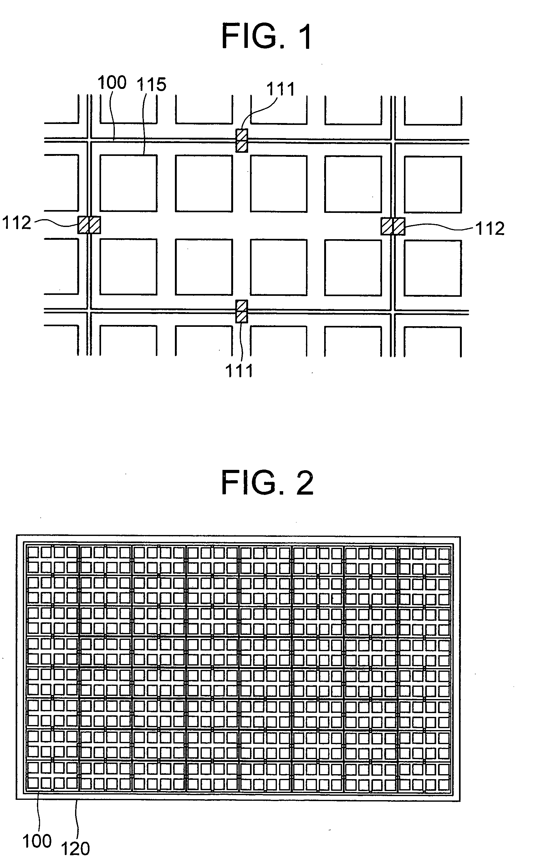
[0036]FIG. 1 illustrates each lighting module used in a lighting unit in the present embodiment.

[0037] Concerning a lighting module 100 in the present embodiment, the outside configuration is a rectangle. Also, the aspect ratio is equal to 16:9, and the diagonal size is equal to 4 times as large as about 1 inch (1 inch˜25.4 mm), i.e., 100 mm (about 4 inches). In addition to this, letting distances between mutually adjacent lighting modules in transverse and longitudinal directions be an order of 1 mm each, the lighting-module spacing in the diagonal direction becomes equal to substantially 4 inches. Namely, by setting the diagonal size of the lighting module 100 to be 100 mm, which is about 1.6 mm smaller than 4 inches, the lighting-module spacing in the diagonal direction becomes equal to substantially 4 inches.

[0038] As illustrated in FIG. 2, these lighting modules 100 are set in such a manner that the lighting modules 100, which are 8×8 in number in the transverse and longitudi...

embodiment 2

[0074] The second embodiment is the same as the first embodiment except for the following features:

[0075] The lighting module 100 in the first embodiment implements no elements other than the light-source components 115 on the lighting module. In addition, the components 115 are implemented on the one-side surface alone. However, the lighting module 100 in the present embodiment implements the LED elements 115, i.e., the light-source components, on the front-surface side, and implements the light-source control components and the electrical connectors on the back-surface side.

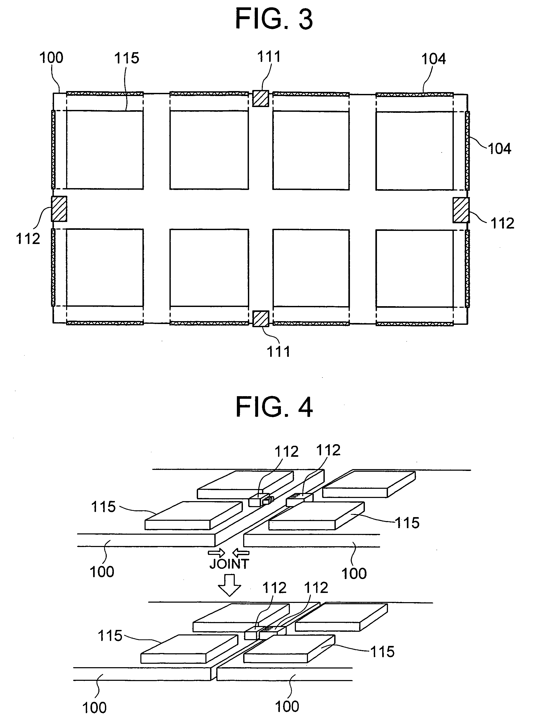
[0076]FIG. 7 illustrates a diagram where the lighting module 100 used in a lighting unit in the second embodiment is seen from the front-surface side.

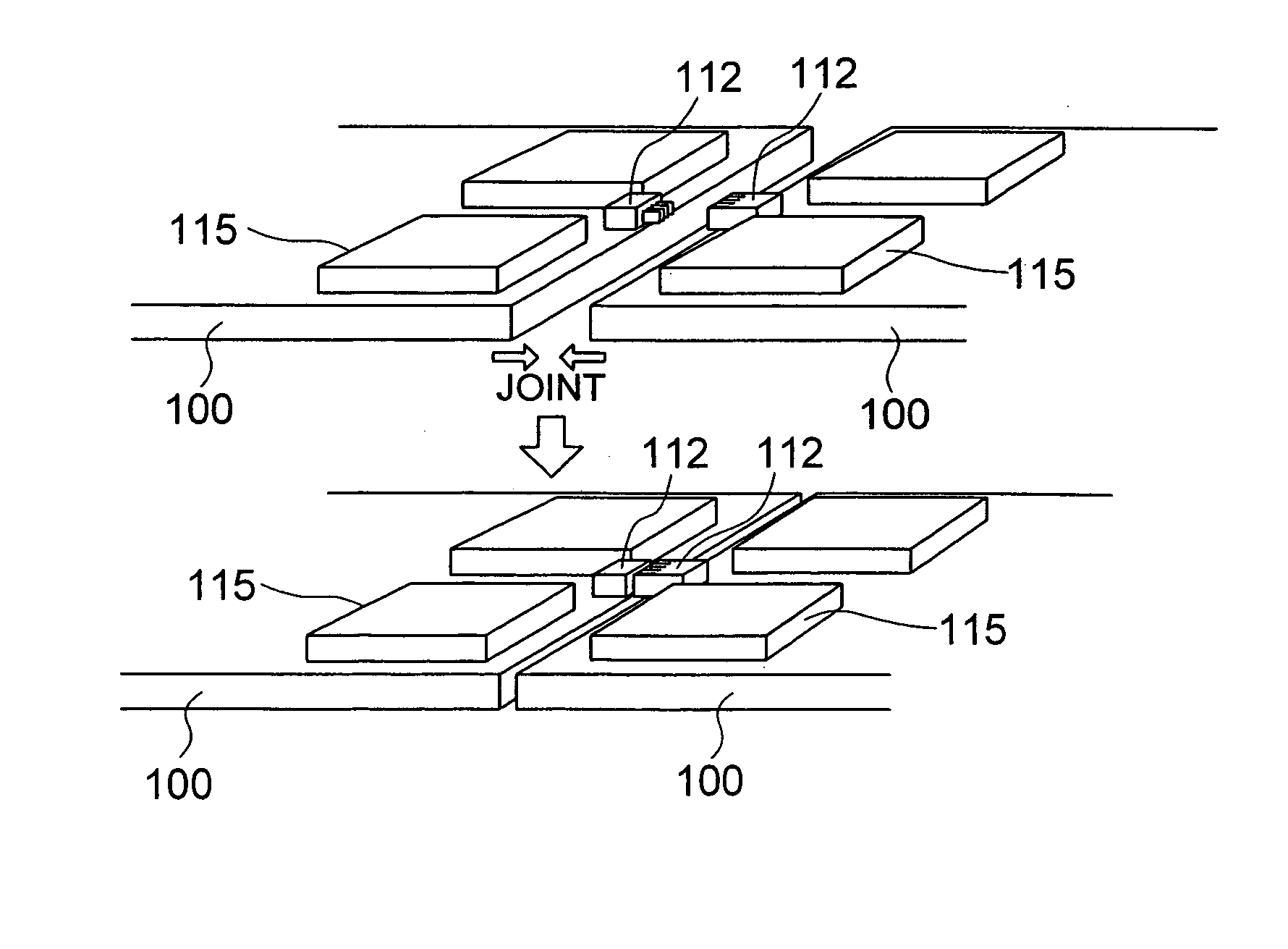
[0077] Although the LED elements 115, i.e., the light-source components, are implemented on the front surface, the longitudinal-direction electrical connectors 111 and the transverse-direction electrical connectors 112 are implemented on the back surface. As a ...

embodiment 3

[0086] The third embodiment is the same as the first embodiment except for the following features:

[0087] In the third embodiment, unlike the first embodiment, the lighting modules whose efficiency levels differ from each other are not used on each place basis in the classified manner. Instead, the low-cost lighting modules at the efficiency level 3 (i.e., ordinary) are used at all the places.

[0088] In the case like this, in the central-portion vicinity of the lighting unit 120, the temperature is more likely to become comparatively higher as compared with the other places. Consequently, the efficiency of the lighting modules in the central-portion vicinity is lowered by the temperature rise as compared with the lighting modules in the peripheral portion. This situation, in some cases, lowers the brightness on average.

[0089] As illustrated in FIG. 11, in the present embodiment, in order to improve the brightness lowering in the central-portion vicinity, a heat sink is provided in ...


PUM


Abstract

There is provided a lighting unit whose area is implemented into a large area by assembling a plurality of lighting modules in a flat-surface-like manner. Moreover, a plurality of electrical connectors are positioned in each lighting module in such a manner that the electrical connectors face each side of each lighting module. Here, the plurality of electrical connectors are mutually connected to the plurality of lighting modules adjacent thereto.

Description

BACKGROUND OF THE INVENTION [0001] The present invention relates to a lighting unit and lighting modules for implementing low-cost display whose display quality is excellent, and a liquid-crystal display using these unit and modules. [0002] Hereinafter, the explanation will be given below concerning a conventional lighting unit and lighting modules, and a liquid-crystal display using these conventional unit and modules. [0003] Up to the present, as displays, a CRT display has been in the mainstream thereof. In recent years, however, an active-matrix liquid-crystal display (which, hereinafter, will be referred to as “LCD”) has been becoming more and more prevalent. The LCD is a display which utilizes light transmittance property of liquid crystal. Namely, the liquid crystal itself emits no light, and performs display by allowing light of a backlight to be transmitted / cutoff. Here, the backlight exists at the rear surface of the liquid crystal. [0004] As most of backlights for this LC...

Claims


Application Information

Patent Timeline
IPC IPC(8): F21S2/00G02F1/13357F21S8/04F21V8/00F21V19/00F21V21/002F21V23/00F21V23/06F21V29/00F21Y101/02H01R33/00
CPCF21S2/005F21V21/002G02F2001/133612G02F1/133603G02F1/133605F21Y2101/02F21Y2115/10G02F1/133612G02F1/1335
Inventor YAMAMOTO, TSUNENORIHIYAMA, IKUOKONNO, AKITOYOKAJITA, DAISUKE
Owner PANASONIC LIQUID CRYSTAL DISPLAY CO LTD
Why Eureka
Try Eureka