Network relay system and control method thereof

a relay system and relay technology, applied in the field of network relay devices, can solve problems such as reducing the total bandwidth

Inactive Publication Date: 2005-12-01
HITACHI LTD +1
View PDF8 Cites 84 Cited by
  • Summary
  • Abstract
  • Description
  • Claims
  • Application Information

AI Technical Summary

Benefits of technology

[0013] The object of the invention is thus to eliminate the drawbacks of the prior art technique and provide a technique of restraining a degenerate mode and s

Problems solved by technology

This prior art technique, however, has the following problems with regard to the redundancy of the link aggregation.
In the case of the occurrence of a trouble in some of the aggregated multiple links, the degenerate mode establishes communication by only normal links and thus un

Method used


Image

  • Network relay system and control method thereof
  • Network relay system and control method thereof
  • Network relay system and control method thereof

Examples


Embodiment Construction

[0040] One mode of carrying out the invention is discussed below as a preferred embodiment in the following sequence: [0041] A. Configuration of Embodiment [0042] B. Connection [0043] C. Drawbacks of Prior Art and Principles of Embodiment [0044] D. Operations of Embodiment [0045] E. Effects of Embodiment [0046] F. Modifications

A. Configuration of Embodiment

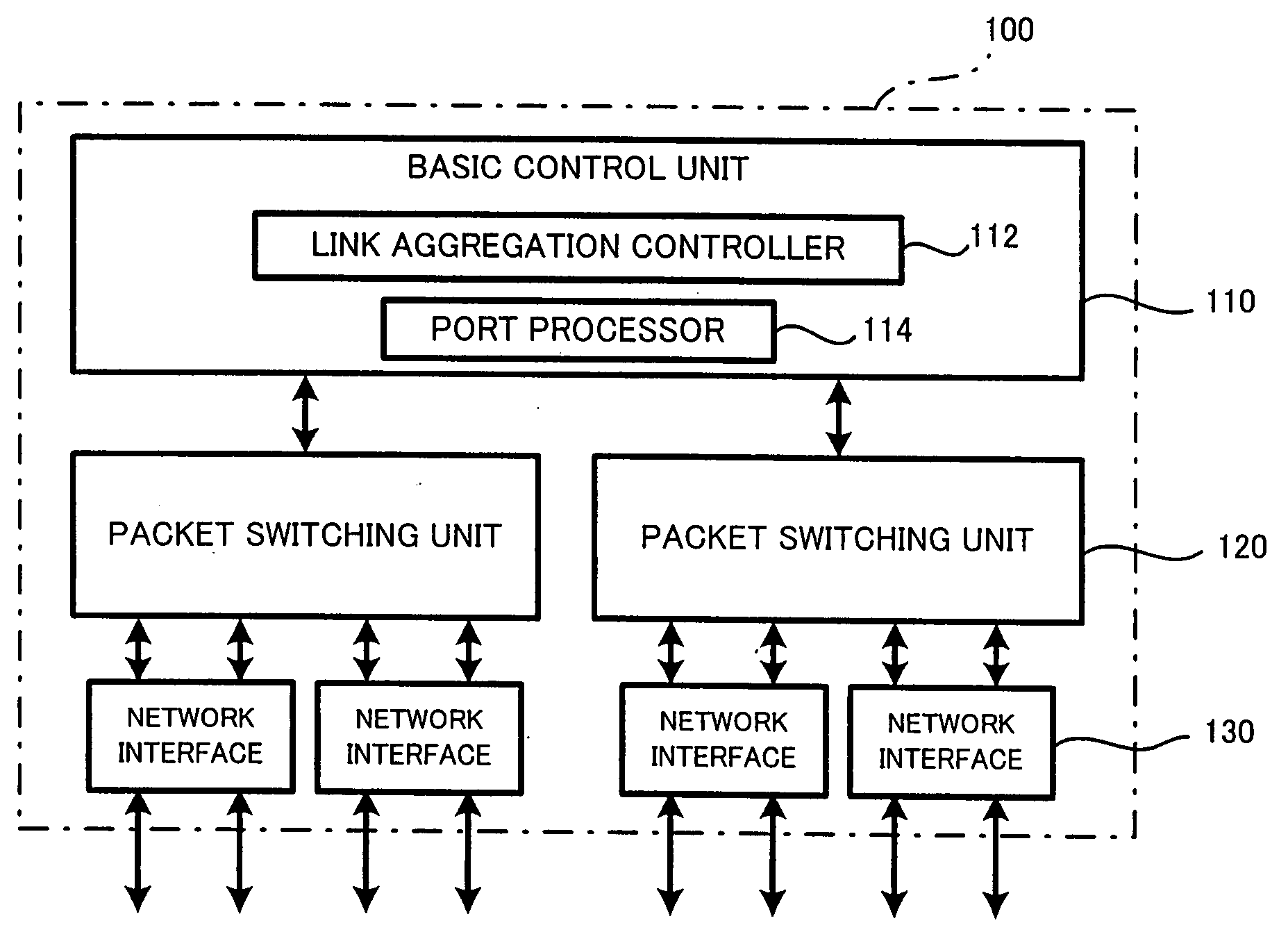
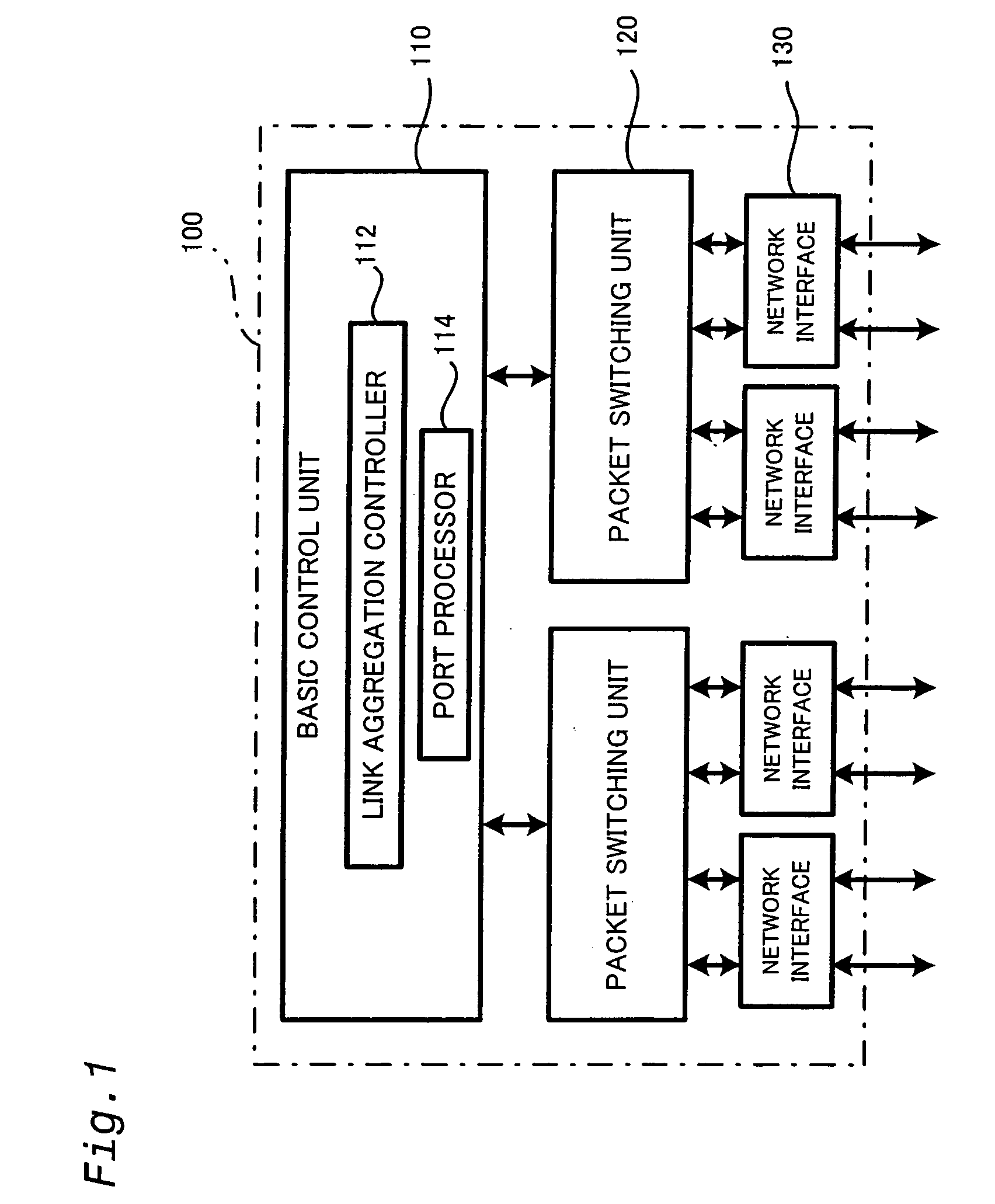
[0047]FIG. 1 is a block diagram showing the configuration of a switch 100 in one embodiment of the invention. As shown in FIG. 1, the switch 100 of this embodiment mainly includes a basic control unit 110 that manages the whole system of the switch 100 and executes routing protocol, packet switching units 120 that carry out packet relay on a second layer (data link layer) of the OSI reference model, and network interfaces 130 that carry out control on a first layer (physical layer). The basic control unit 110 has multiple CPUs and memories (not shown). The multiple CPUs execute programs stored in the memories to respectively fu...


PUM


Abstract

The network relay device of the invention carries out data transmission to and from an opposite device to relay data in a network. The network relay device includes: multiple ports connecting with corresponding multiple ports of the opposite device via multiple links; and a link aggregation control module that aggregates the multiple links to establish a link aggregation, which is regarded as one logic link, and carries out transmission of a control frame signal including a synchronization bit, as well as data transmission, at each port via the link aggregation. In response to detection of occurrence of a trouble in at least one of the aggregated multiple links, the link aggregation control module causes a port that connects with a normal link without the trouble among the multiple ports to stop the data transmission and send the control frame signal including the synchronization bit set equal to a first value. Here the first value functions to stop the data transmission at a corresponding port of the opposite device connecting with the normal link.

Description

BACKGROUND OF THE INVENTION [0001] 1. Field of the Invention [0002] The present invention relates to a network relay device that carries out data transmission to and from an opposite device, so as to relay data in a network. [0003] 2. Description of the Related Art [0004] A switch as one of network relay devices may be designed to have the function of link aggregation, which connects with another switch by multiple links (multiple physical lines) and aggregates the multiple links as one logic link. [0005] One known example of the link aggregation is disclosed in Japanese Patent Laid-Open Gazette No. 2002-26909. [0006] The bandwidth of the logic link is the total of the individual bandwidths of the aggregated multiple links. The link aggregation thus advantageously expands the bandwidth. Even in the case of the occurrence of a trouble or failure in some of the aggregated multiple links, the link aggregation adopts a degenerate mode to continue communication via the remaining normal l...

Claims


Application Information

Patent Timeline
IPC IPC(8): H04J3/06H04L12/28H04L69/40
CPCH04L49/351H04L49/557H04L49/555
Inventor SUZUKI, MASASHIFUJITA, MANABUISOGAI, HIROYUKINOZAKI, SHINJI
Owner HITACHI LTD
Why Eureka
Try Eureka