
C-arm device with adjustable detector offset for cone beam imaging involving partial circle scan trajectories

a technology of partial circle scan and detector offset, which is applied in the field of carm xray system, can solve the problems of not being not practical to achieve, and proposed solutions that are not easily applicable to c-arm x-ray system

Inactive Publication Date: 2005-12-01
SIEMENS MEDICAL SOLUTIONS USA INC
View PDF10 Cites 35 Cited by
  • Summary
  • Abstract
  • Description
  • Claims
  • Application Information

AI Technical Summary

Benefits of technology

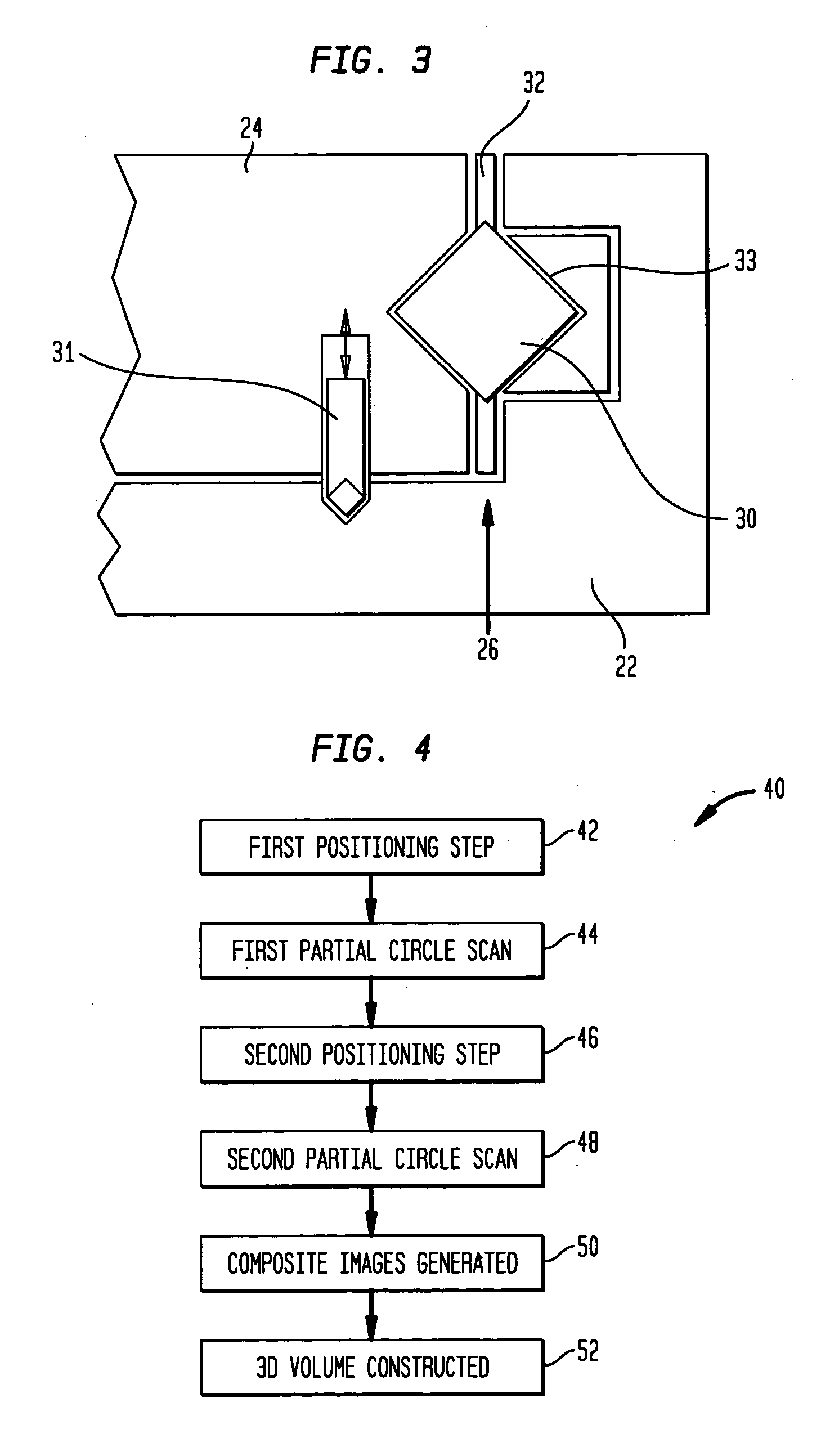
[0010] According to another aspect of the invention, a method is provided for taking two partial circle scans with center stage of the detector is opposite offset positions creating an effective detector of larger size to avoid the problems of truncated projections.

Problems solved by technology

Given the detector size and the object to be imaged, this is often not practical to achieve.
Both of these proposed solutions are not easily applicable to a C-arm X-ray system.
While this method increase the effective detector width, it is not applicable to C-arm X-ray systems as they can not perform complete circle scans but rather only partial circle scans.

Method used


Image

  • C-arm device with adjustable detector offset for cone beam imaging involving partial circle scan trajectories
  • C-arm device with adjustable detector offset for cone beam imaging involving partial circle scan trajectories
  • C-arm device with adjustable detector offset for cone beam imaging involving partial circle scan trajectories

Examples


Embodiment Construction

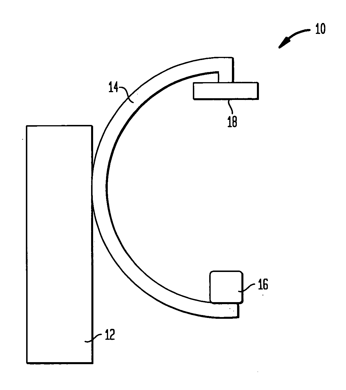
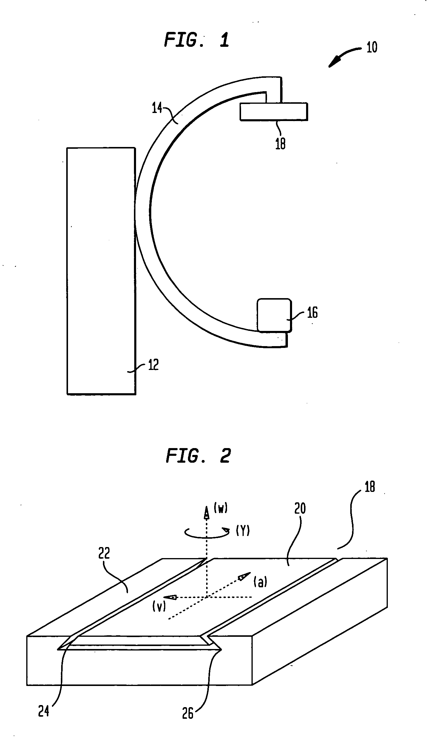
[0019] Referring to FIG. 1, a C-arm X-ray imaging system 10, having a gantry 12 supporting a C-arm 14. The C-arm 14 has atone end an X-ray source 16 and a detector 18 at the other end. The C-arm 14 defines a plane. The C-arm nay swivel in the around an axis perpendicular to the pane in process called angulation. The C-arm 14 may also swivel around an axis perpendicular to the pane in orbital rotation. During a partial circle scan, the C-arm 14 will angulate to generate views from multiple angles. The detector 18 itself rotates around the axes defined by the detector 18 and the source 16.

[0020] In an one embodiment of the present invention, the detector 18 may be a free bilateral offset detector as shown in FIG. 2. The detector 18 has a central stage 20 and a detector mount 22. The detector mount 22 includes slides 24 and 26 to hold and translate the central stage 30. The slides 24 and 26 may be dove tails other structures well known to the mechanical arts.

[0021] In one embodiment ...


PUM

PropertyMeasurementUnit
volumeaaaaaaaaaa
sizeaaaaaaaaaa
widthaaaaaaaaaa

Abstract

Method and system of generating a three dimensional reconstruction of a volume of a patient with an C-arm X-ray imaging system. More particularly, the method and system taught corrects for truncation projection errors by creating an effective detector of greater width.

Description

BACKGROUND OF THE INVENTION [0001] 1. Field of the Invention [0002] The present invention generally relates to C-arm X-ray system used for medical imaging. In particular, the present invention relates to a novel method and system for the correction of truncated projections that occur in such C-arm X-ay systems. [0003] 2. Description of the Background Art [0004] C-arm X-ray systems are currently used in medical imaging to create both 2-D and 3-D images (reconstructions). These systems Many C-arm X-ray systems, like other practical cone-beam imaging devices, are equipped with detectors that are to small to fully capture a projection of a given object. Such detectors cause truncated projections when recording views of objects that extend beyond the detector boundaries. Since the Detector Field of View (DFOV) determines the Scan Field of View (SFOV) a small detector limits the overall size of an object that can be examined and reconstructed without artifacts. [0005] Mathematical extrapo...

Claims


Application Information

Patent Timeline
Patent Type & Authority Applications(United States)
IPC IPC(8): A61B6/00A61B6/02A61B6/03G01N23/00G01N23/04G06T11/00H05G1/02
CPCA61B6/032A61B6/4085A61B6/027A61B6/583G01N23/04A61B6/4441
Inventor STROBEL, NORBERT KARL
Owner SIEMENS MEDICAL SOLUTIONS USA INC
Learn More