Balance assembly for rotary turbine component and method for installing and/or adjusting balance weight

a technology of rotary turbines and components, which is applied in the direction of marine propulsion, vessel construction, instruments, etc., can solve the problems of inaccessible balance weights, unable to synchronize the weight distribution of the balance assembly, and the inability to fully disassemble the balance assembly

Inactive Publication Date: 2005-12-01
GENERAL ELECTRIC CO
View PDF36 Cites 36 Cited by
  • Summary
  • Abstract
  • Description
  • Claims
  • Application Information

AI Technical Summary

Benefits of technology

[0014] (2) move the at least one balance weight towards the bottom surface so that the shoulder surfaces do not engage the side walls at the balance weight engaging section such that the at least one balance weight is in a unsecured position within the slot.

Problems solved by technology

A problem with certain balancing systems for rotors is that trim balancing or rebalancing of the rotors can require partial or complete disassembly of the engine in order to access the balance weights.
As a result, these balance weights are usually inaccessible without at least partial disassembly of the engine.
Such access ports or openings can cause a lack of symmetry in weight distribution of the balance assembly, as well as creating potential weaknesses in the balance assembly with regard to the concentration of stresses.
Some of these balance systems can require that the balance weight be inserted at a specific location, thus making finer balance adjustments more difficult to achieve.

Method used


Image

  • Balance assembly for rotary turbine component and method for installing and/or adjusting balance weight
  • Balance assembly for rotary turbine component and method for installing and/or adjusting balance weight
  • Balance assembly for rotary turbine component and method for installing and/or adjusting balance weight

Examples


Embodiment Construction

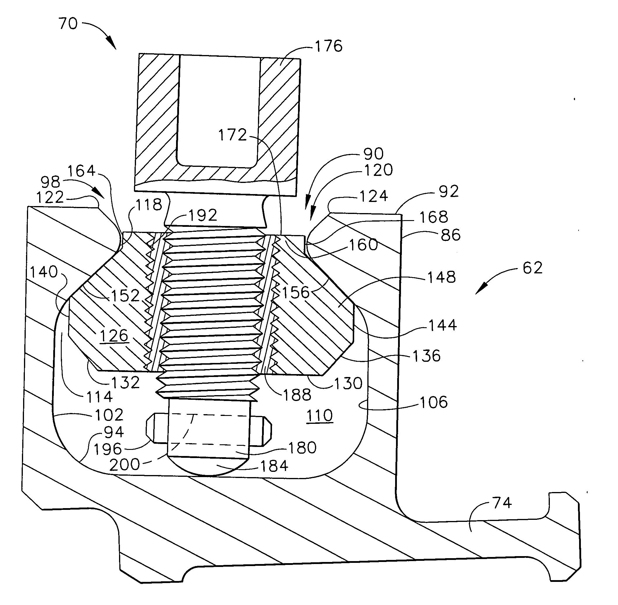
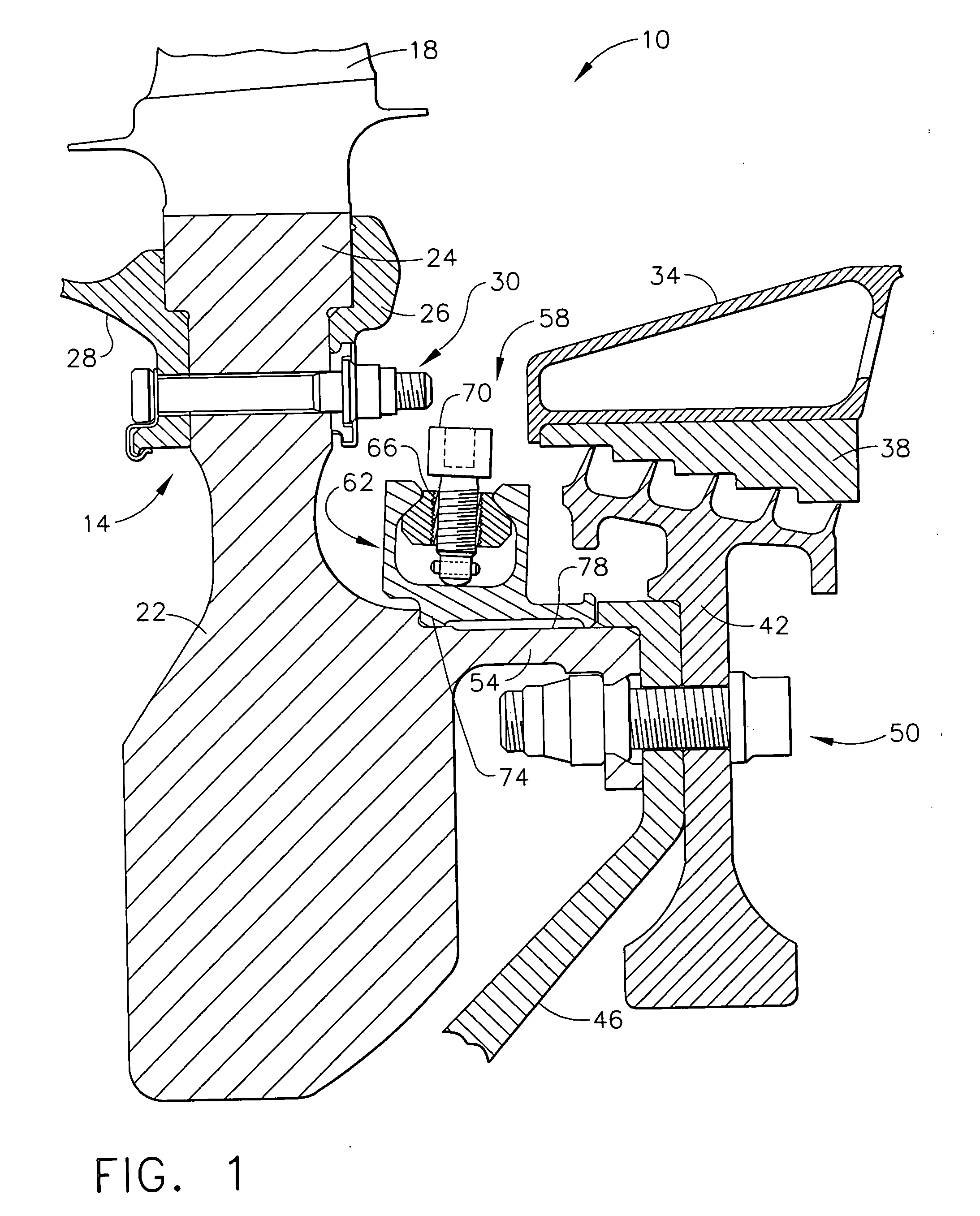
[0026] Referring to the drawings, FIG. 1 illustrates a fragmentary cross-section of a representative section of a turbine engine that is indicated generally as 10 in which the balance assembly of this invention can be used. Turbine engine section 10 is shown as having a turbine rotor indicated generally as 14. Turbine engine section 10 can be any section having such a rotor 14, including but not limited to a high pressure (HP) compressor section, a low pressure (LP) compressor section, an HP turbine section, a LP turbine section, an intermediate power (IP) turbine section, or a power (PW) turbine section. In other words, the turbine engine section 10 shown in FIG. 1, and as described hereafter, should be considered only representative of the use of the embodiment of the balance assembly of this invention.

[0027] As shown in FIG. 1, rotor 14 comprises a plurality of circumferentially spaced turbine blades, one of which is indicated as 18, that extend radially from a central hub or di...


PUM


Abstract

A balance assembly for turbine rotating components, such as turbine rotors, as well as method for installing and/or adjusting at least one balance weight in the balance assembly and turbine section having this balance assembly and a radially extending access pathway for accessing this balance assembly. The balance assembly comprises; (a) a balance weight retention member having a circumferential periphery and a slot formed therein along at least a portion thereof, the slot having: (1) a bottom surface; (2) an opening; and (3) a pair of spaced apart and opposed side walls connecting the bottom surface and the opening, the side walls sloping inwardly between the bottom surface and the opening to define a balance weight engaging section; (b) at least one balance weight configured and sized to be insertable through the opening of the slot and to be positionable for movement within the slot and having a pair of spaced apart generally inwardly sloping shoulder surfaces capable of engaging the side walls of the slot at the balance weight engaging section; and (c) a balance weight securing member associated with the at least one balance weight that can be actuated to: (1) move the at least one balance weight away from the bottom surface so that the shoulder surfaces engage the side walls at the balance weight engaging section such that the at least one balance weight is in a secured position within the slot; or (2) move the at least one balance weight towards the bottom surface so that the shoulder surfaces do not engage the side walls at the balance weight engaging section such that the at least one balance weight is in a unsecured position within the slot.

Description

BACKGROUND OF THE INVENTION [0001] This invention relates generally to a balance assembly for a rotary turbine component such as a turbine rotor. This invention also relates to a method for installing one or more balance weights in this balance assembly, as well as adjusting the balance weight(s) after installation. This invention further relates to a turbine section having this balance assembly and a radially extending access pathway for accessing this balance assembly. [0002] In the production of turbine engines, the balancing of the rotary turbine components, such as turbine rotors, can be an essential and important step. The turbine rotors are typically balanced initially prior to the actual assembly of the engine. This balancing can be achieved in variety of ways, for example, by the attachment of special weights designed to fit on bolts or within grooves of the rotor or associated components, or by grinding material from specified sections on the rotor. See U.S. Pat. No. 4,220...

Claims


Application Information

Patent Timeline
Patent Type & Authority Applications(United States)
IPC IPC(8): F01D5/02F01D5/00F01D5/10F01D25/00F01D25/04F16F15/32F16F15/34G01M1/36
CPCF01D5/027F16F15/34F16F15/322F04D29/662
Inventor PRZYTULSKI, JAMES CHARLESMCGREEHAN, WILLIAM FRANCISALTMAN, JOHN EDWARDSHAUB, CLARENCE J.CECCOPIERI, FERNANDO
Owner GENERAL ELECTRIC CO
Why Eureka
Try Eureka