Torque vectoring drive axle assembly

Inactive Publication Date: 2005-12-01
NEW VENTURE GEAR INC
View PDF36 Cites 15 Cited by
  • Summary
  • Abstract
  • Description
  • Claims
  • Application Information

AI Technical Summary

Benefits of technology

[0005] Accordingly, it is an objective of the present invention to provide a drive axle assembly for use in motor vehicles which is equipped with an adaptive yaw control system.
[0006] To achieve this objective, the drive axle assembly of the present invention includes first and second axleshafts connected to a pair of wheels and a torque distributing drive mechanism that is operable for transferring drive torque from a driven input shaft to the first and second axleshafts. The torque distributing drive mechanism includes a differential, a speed changing unit, and first and second mode clutches. The differential includes an input component driven by the input shaft, a first output component driving the first axleshaft and a second output component driving the second axleshaft. The speed changing unit includes a first shaft commonly driven with the first axleshaft, a second shaft commonly driven with the second axleshaft, and first and second gearsets driven by the first shaft. The first mode clutch is operable for selectively coupling the first gearset to the second shaft. Likewise, the second mode clutch is operable for selectively coupling the second gearset to the second shaft. Accordingly, selective control over actuation of

Problems solved by technology

As such, engagement of the first mode clutch results in the sec

Method used


Image

  • Torque vectoring drive axle assembly
  • Torque vectoring drive axle assembly
  • Torque vectoring drive axle assembly

Examples


Embodiment Construction

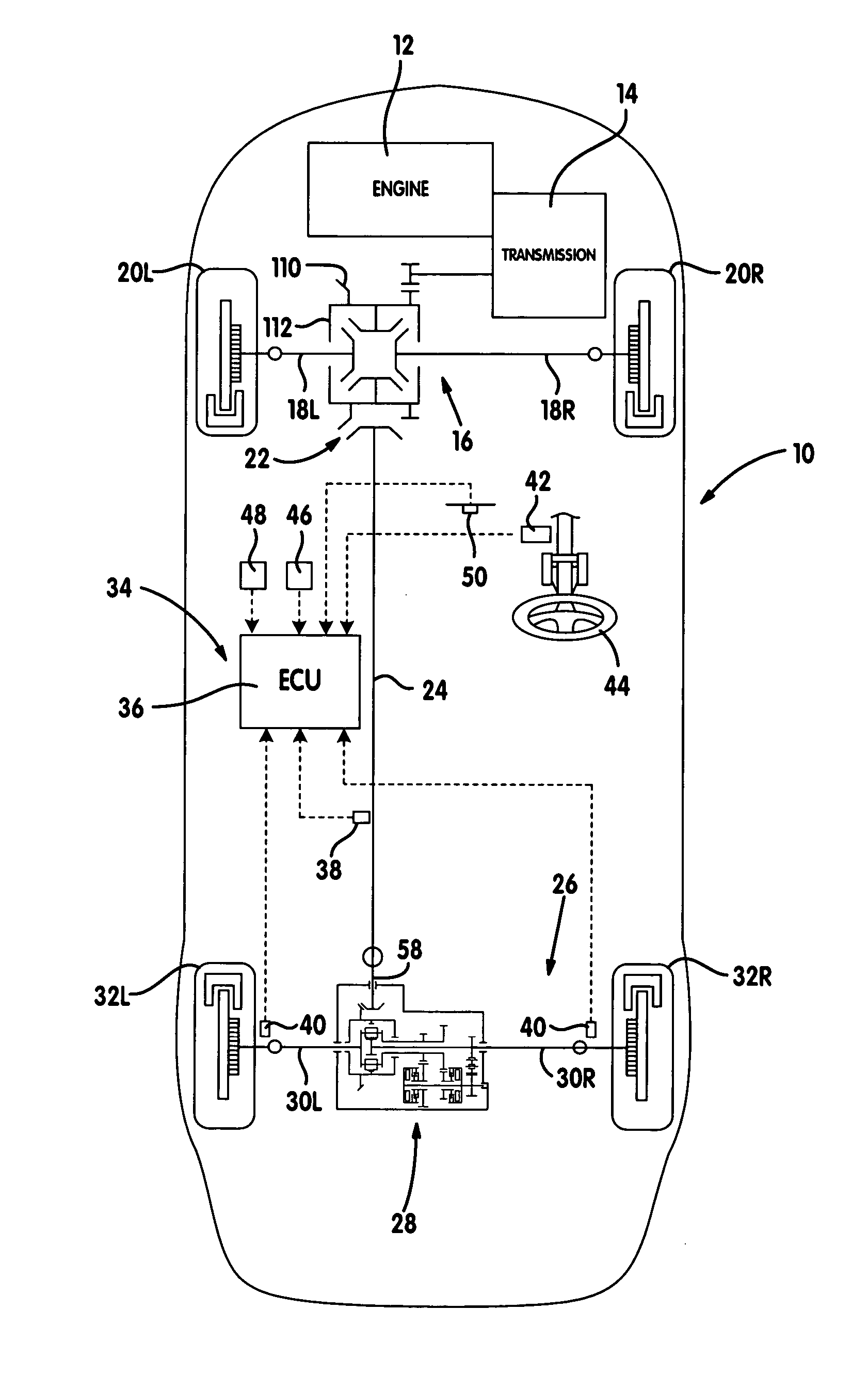
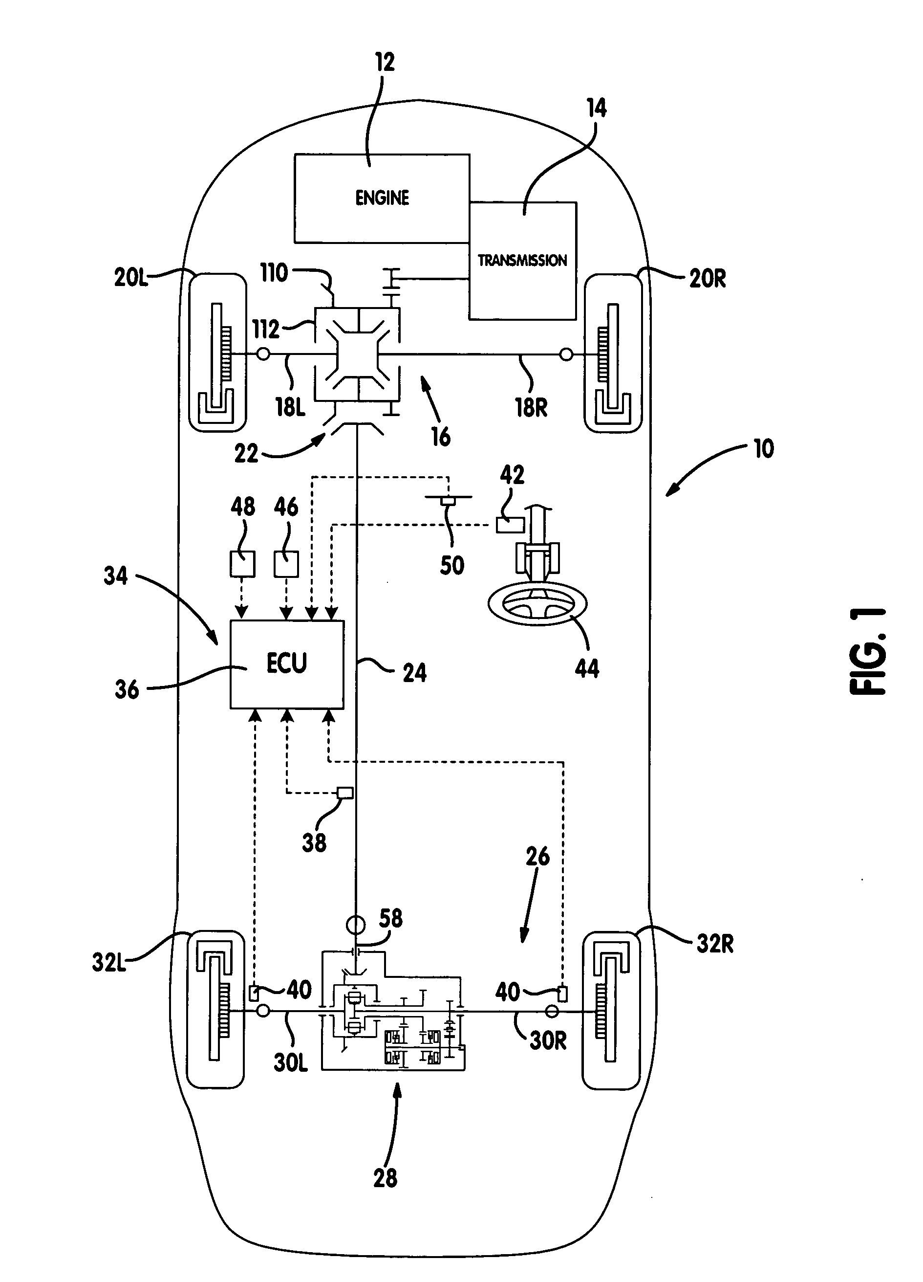
[0018] Referring to FIG. 1, an all-wheel drive vehicle 10 includes an engine 12 transversely mounted in a front portion of a vehicle body, a transmission 14 provided integrally with engine 12, a front differential 16 which connects transmission 14 to front axleshafts 18L and 18R and left and right front wheels 20L and 20R, a power transfer unit (“PTU”) 22 which connects front differential 16 to a propshaft 24, and a rear axle assembly 26 having a torque distributing drive mechanism 28 which connects propshaft 24 to axleshafts 30L and 30R for driving left and right rear wheels 32L and 32R. As will be detailed, drive mechanism 28 is operable in association with a yaw control system 34 for controlling the transmission of drive torque through axleshafts 30L and 30R to rear wheels 32L and 32R.

[0019] In addition to an electronic control unit (ECU) 36, yaw control system 34 includes a plurality of sensors for detecting various operational and dynamic characteristics of vehicle 10. For exa...


PUM


Abstract

A drive axle assembly includes first and second axleshafts connected to a pair of wheels and a drive mechanism operable to selectively couple a driven input shaft to one or both of the axleshafts. The drive mechanism includes a differential, a speed changing unit operably disposed between the differential assembly and one of the first and second axleshafts, and first and second mode clutches. The first mode clutch is operable to decrease the rotary speed of the second axleshaft which, in turn, causes a corresponding increase in the rotary speed of the first axleshaft. The second mode clutch is operable to increase the rotary speed of the second axleshaft so as to cause a decrease in the rotary speed of the first axleshaft. A control system controls actuation of both mode clutches.

Description

FIELD OF THE INVENTION [0001] The present invention relates generally to differential assemblies for use in motor vehicles and, more specifically, to a differential assembly equipped with a torque vectoring drive mechanism and an active control system. BACKGROUND OF THE INVENTION [0002] In view of consumer demand for four-wheel drive vehicles, many different power transfer system are currently utilized for directing motive power (“drive torque”) to all four-wheels of the vehicle. A number of current generation four-wheel drive vehicles may be characterized as including an “adaptive” power transfer system that is operable for automatically directing power to the secondary driveline, without any input from the vehicle operator, when traction is lost at the primary driveline. Typically, such adaptive torque control results from variable engagement of an electrically or hydraulically operated transfer clutch based on the operating conditions and specific vehicle dynamics detected by sen...

Claims


Application Information

Patent Timeline
IPC IPC(8): B60K23/04B60W10/10F16D48/06F16H37/08
CPCB60K23/04B60W10/14F16D48/06F16D2500/10425F16H2048/04F16D2500/3115F16H48/10F16H48/22F16D2500/1045
Inventor BOWEN, THOMAS C.
Owner NEW VENTURE GEAR INC
Why Eureka
Try Eureka