Washing machine gearbox

a technology for washing machines and gearboxes, applied in other washing machines, washing apparatuses, textiles and papermaking, etc., can solve the problems of cost and durability inconvenience, early loss of users of washing machines, etc., and achieve the effect of improving the distribution and transmission of motive power, reducing the cost and improving the service li

Inactive Publication Date: 2005-12-01
BOURQUIM RENE +1
View PDF16 Cites 3 Cited by
  • Summary
  • Abstract
  • Description
  • Claims
  • Application Information

AI Technical Summary

Benefits of technology

[0008] It is also an aspect of the present invention to provide a gearbox model for the vertical shafts of washing machines of low cost that combines the requisites of robustness, safety and utilitarian practicality, thus offering the consumer countless possibilities and benefits.
[0009] It is yet another aspect of the present invention to provide a new mechanical design of the cylindrical gearbox, being preferably made of high-resistance polymer, so as to enable the application of a set of epicycloidal gears, comprising the sun gear, satellite gears that form a planetary assembly, and the annular gear on the inner perimeter of the cylindrical gearbox. This new constructive arrangement contributes toward a better distribution and transmission of the motive power.
[0010] The present invention thus employs a gearbox with desirable mechanical and functional qualities and also has a novel shape, arrangement and location of parts and components that increase the efficiency without any burden whatsoever. The present invention is also designed with the intention of creating a device that is more efficient, longer-lasting, light and that is inexpensive to produce conveniently embodied and arranged to perform its functions with unmatched efficiency and versatility, without the abovementioned inconveniences.

Problems solved by technology

In its ordinary form, the above device works and meets the minimum mechanical performance required by experts and engineers in the field, however, there are also inconveniences related to cost and durability since the cylindrical gears contained in the cylindrical gearbox wear out in time because they work without support such as teeth located on the inner surface of the cylindrical gearbox.
This lack of support is due to the impossibility of making a tooth track in the inner perimeter of the cast metal cylindrical box.
Further, cylindrical gearboxes are traditionally heavy and indirectly wear out the cylindrical gears arranged in the interior thereof, bringing early losses to the users of washing machines.

Method used


Image

  • Washing machine gearbox
  • Washing machine gearbox
  • Washing machine gearbox

Examples


Embodiment Construction

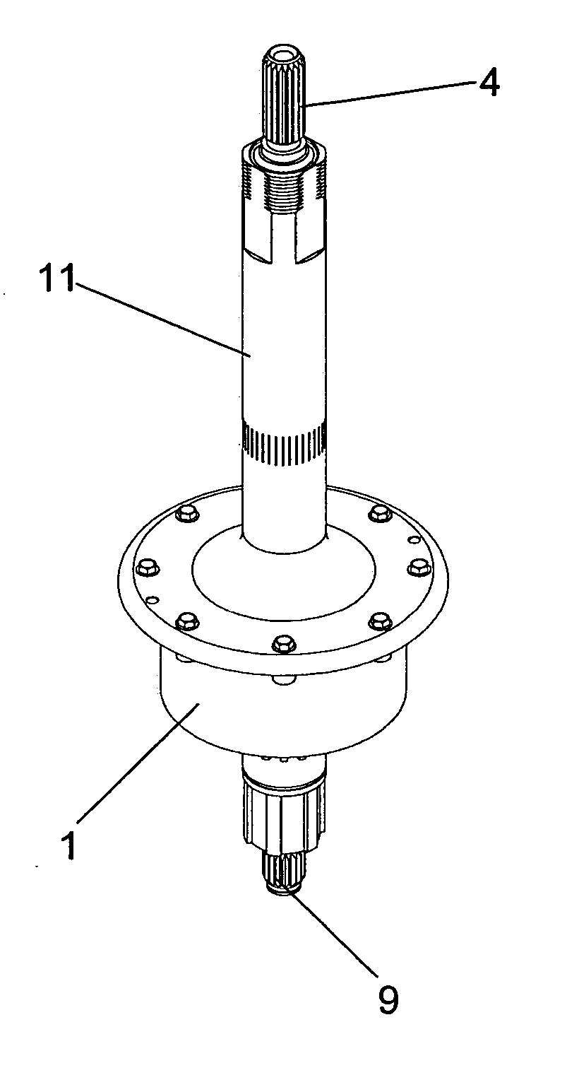
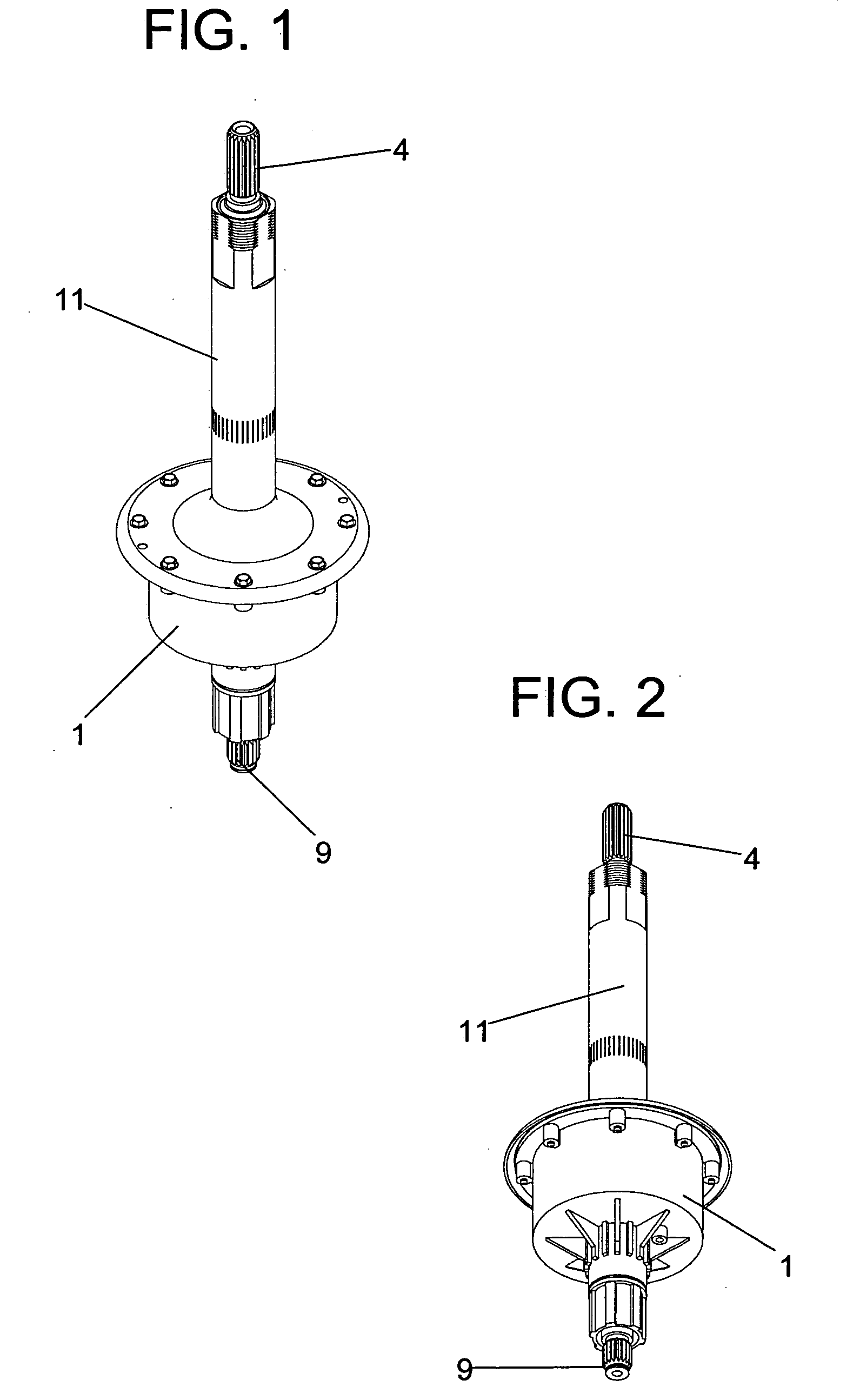
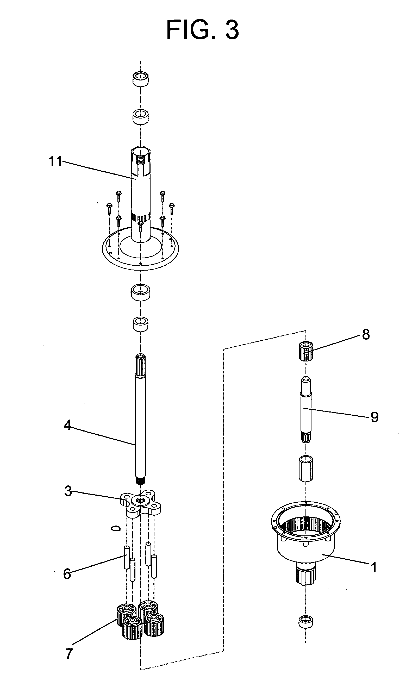
[0029] Referring now to FIGS. 1-9, a washing machine gearbox 1 is shown that is preferably made of a high-resistance polymer, and which is equipped in its inner perimeter with an annular gear 2 that meshes with four planetarily arranged epicycloidal gears 7, that are rotatably interconnected to a support 3 via four perpendicular shafts 6. The support 3 is in turn connected to a secondary shaft 4 that is connected to a central washing agitator 5. The teeth of the gears 7 interface with those of the annular ring 2, and the teeth of a sun gear 8. The sun gear 8 is coupled to the end of the shaft 9 that projects through a central part of the cylindrical box 1 and is oscillated by a transmission assembly of the washing machine 10. The gear proportions are customized such that the planetary gears 7 pertaining to the planetary assembly follow the rotational motion of the sun gear 8 at a lower speed and in the same direction. The cylindrical gearbox 1, together with an outer shaft 11, is co...


PUM


Abstract

A new and improved washing machine gearbox for interaction with an agitating shaft is provided that possesses greater durability, lightness and uniformity in the transmission of the motive force than gearboxes in the art. Preferably, the gearbox comprises a cylindrical box, preferentially made of high-resistance polymer and equipped in its inner perimeter with an annular gear that meshes with epicycloidal gears formed by a planetary assembly.

Description

[0001] This application claims the benefit of Brazilian Utility Model Application Serial No. MU8400820, filed Apr. 29, 2004, which is incorporated by reference in its entirety herein. This application is also related to Brazilian Utility Model Application Serial Nos. MU8400819 and MU8401086, filed Apr. 29, 2004 and May 24, 2004, respectively, which are both incorporated by reference in their entirety herein. FIELD OF THE INVENTION [0002] The present invention is an improved mechanical device to be utilized in a common washing machine. More specifically, one embodiment of the present invention utilizes a gearbox coupled to the agitator shaft of a vertical washing machine that is aimed at improving its utilization and performance in relation to other models usually found in the market. BACKGROUND OF THE INVENTION [0003] It is widely known that household appliances offer great help in the performance of various domestic chores. With respect to clothes washing, the technical sphere has ...

Claims


Application Information

Patent Timeline
Patent Type & Authority Applications(United States)
IPC IPC(8): D06F37/40F16H1/28F16H37/02F16H37/12
CPCF16H1/28D06F37/40
Inventor BOURQUIM, RENEGALVES, RENE BOURQUIM
Owner BOURQUIM RENE
Why Eureka
Try Eureka