Removable vena cava filter

a filter and vena cava technology, applied in the field of medical devices, can solve the problems of filter generally not being considered to be removable from patients, thrombosis a serious risk of pulmonary embolism, thrombosis, etc., and achieve the effect of reducing the potential of struts, enhancing the centering capability, and reducing the engagement between struts and blood vessels

Active Publication Date: 2005-12-01
COOK MEDICAL TECH LLC
View PDF41 Cites 81 Cited by
  • Summary
  • Abstract
  • Description
  • Claims
  • Application Information

AI Technical Summary

Benefits of technology

[0015] In certain embodiments, pairs of secondary struts are positioned between pairs of primary struts. Each pair of secondary struts is twisted together near the connected ends of the secondary struts to form a twisted section. The twisted sections of the secondary struts effectively stiffen the struts to enhance their centering capabilities to prevent the filter from tilting when the filter is deployed in the blood vessel. Hence, engagement between the struts and the blood vessel is minimized which reduces the potential for the struts to become endothelialized within the blood vessel. A further feature of the twisted sections is that they prevent or at least minimize the secondary struts from entangling with the primary struts.

Problems solved by technology

During such medical conditions, the need for filtering devices arises due to the likelihood of thrombosis in the peripheral vasculature of patients wherein thrombi break away from the vessel wall, risking downstream embolism or embolization.
For example, depending on the size, such thrombi pose a serious risk of pulmonary embolism wherein blood clots migrate from the peripheral vasculature through the heart and into the lungs.
For example, filters generally have not been considered removable from a patient due to the likelihood of endotheliosis of the filter or fibrous reaction matter adherent to the endothelium during treatment.
As a result, the filter including the hub and the retrieval hook engage the vessel wall along their lengths and potentially become endothelialized therein.
In the event of this occurrence, there is a greater likelihood of endotheliosis of the filter to the blood vessel along a substantial length of the filter wire.
It has been a challenge to design a vena cava filter with features that lessen the concerns of undesirably scratching or scraping of the anchoring hooks against outer walls of an introducer tube or a blood vessel while maintaining the effectiveness of the filter.

Method used


Image

  • Removable vena cava filter
  • Removable vena cava filter
  • Removable vena cava filter

Examples


Embodiment Construction

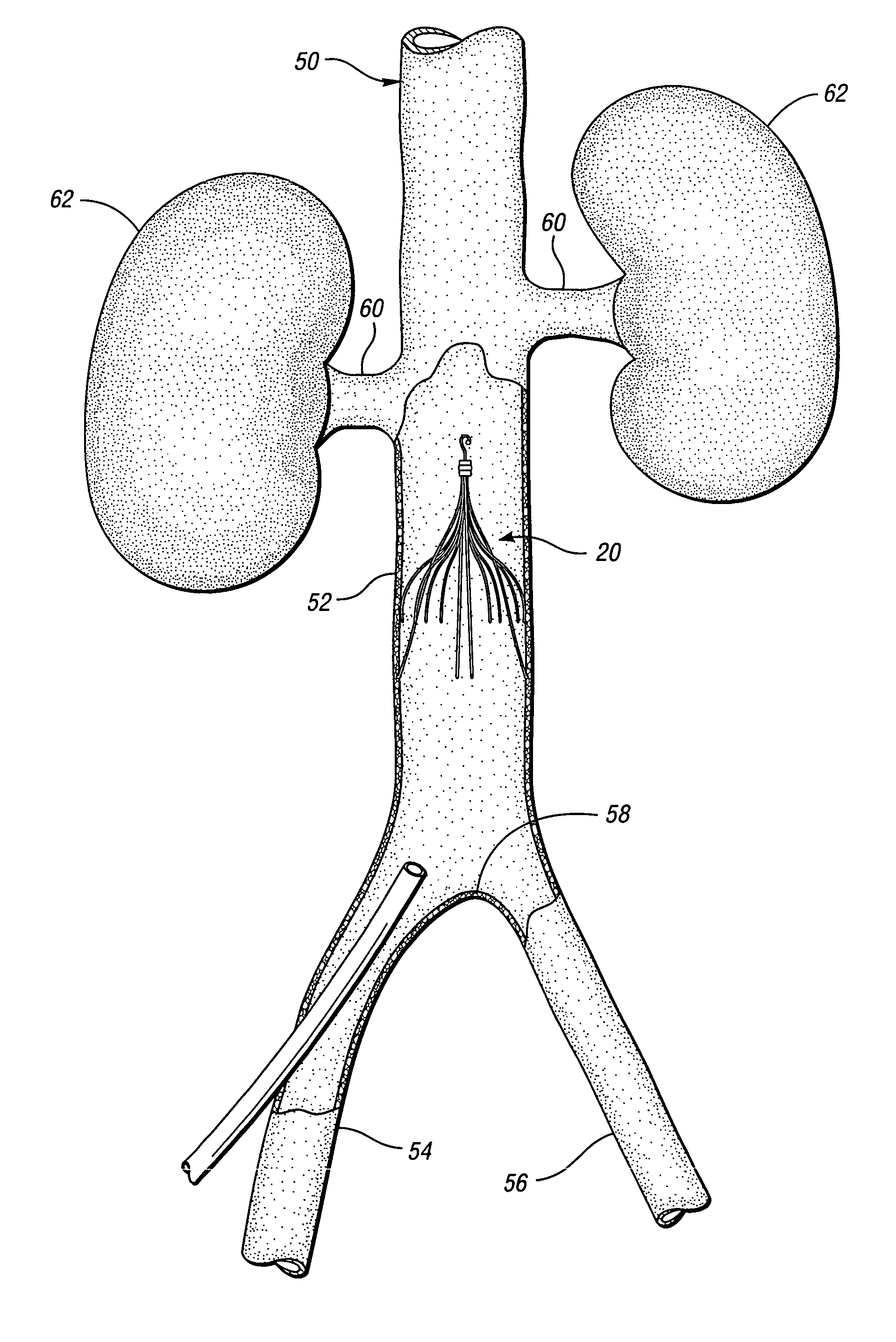
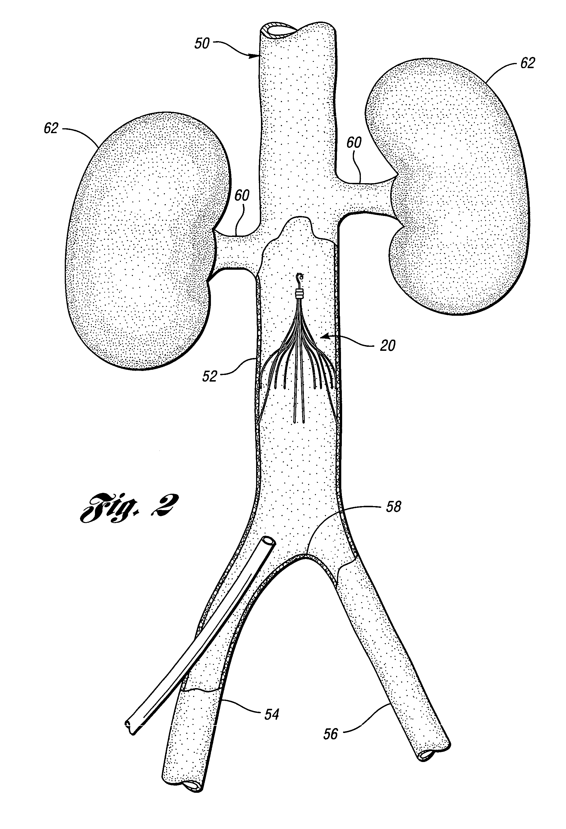
[0033] In accordance with one embodiment of the present invention, FIG. 2 illustrates a vena cava filter 10 implanted in the vena cava 50 for the purpose of lysing or capturing thrombi carried by the blood flowing through the iliac veins 54, 56 toward the heart and into the pulmonary arteries. As shown, the iliac veins merge at juncture 58 into the vena cava 50. The renal veins 60 from the kidneys 62 join the vena cava 50 downstream of juncture 58. The portion of the vena cava 50, between the juncture 58 and the renal veins 60, defines the inferior vena cava 52 in which the vena cava filter 10 has been percutaneously deployed through one of the iliac veins 54. Preferably, the vena cava filter 10 has a length smaller than the length of the inferior vena cava 52. If the lower part of the filter extends into the iliac veins, filtering effectiveness will be compromised and if the filter wires cross over the origin of the renal veins the filter wires might interfere with the flow of bloo...


PUM


Abstract

The present invention provides a removable vena cava filter for capturing thrombi in a blood vessel. The filter comprises a plurality of primary struts having first ends attached together along a longitudinal axis. Each primary strut includes an arcuate segment having a first tensile strength. The arcuate segment extends from the first end to an anchoring hook. The anchoring hook is integral with the arcuate segment and having the first thickness and first tensile strength. The filter further comprises a plurality of secondary struts freely spaced between the primary struts and having connected ends attached together along the longitudinal axis. Each secondary strut freely extends from the connected end to a free end avoiding contact with other secondary struts and primary struts. Each secondary strut has a second tensile strength.

Description

CROSS-REFERENCE TO RELATED APPLICATIONS [0001] This application claims the benefit of U.S. Provisional Application Ser. No. 60 / 563,243, filed on Apr. 16, 2004, entitled “REMOVABLE VENA CAVA FILTER,” the entire contents of which are incorporated herein by reference. [0002] This application also claims the benefit of U.S. Provisional Application No. 60 / 562,813, filed on Apr. 16, 2004, entitled “REMOVABLE FILTER FOR CAPTURING BLOOD CLOTS,” the entire contents of which are incorporated herein by reference. [0003] This application also claims the benefit of U.S. Provisional Application No. 60 / 562,909, filed on Apr. 16, 2004, entitled “BLOOD CLOT FILTER WITH STRUTS HAVING AN EXPANDED REMEMBERED STATE,” the entire contents of which are incorporated herein by reference. [0004] This application also claims the benefit of U.S. Provisional Application No. 60 / 563,176, filed on Apr. 16, 2004, entitled “BLOOD CLOT FILTER HAVING A COLLAPSED REMEMBERED STATE,” the entire contents of which are incor...

Claims


Application Information

Patent Timeline
Patent Type & Authority Applications(United States)
IPC IPC(8): A61F2/01A61M29/00
CPCA61F2/01A61F2002/011A61F2230/008A61F2230/005A61F2002/016A61F2/0105A61F2/011
Inventor OSBORNE, THOMAS A.MOLGAARD-NIELSEN, ARNEHENDRIKSEN, PERGUNTHER, ROLF
Owner COOK MEDICAL TECH LLC
Why Eureka
Try Eureka