Accommodating intraocular lens system with aberration-enhanced performance

a technology of aberration and lens system, applied in intraocular lens, medical science, prosthesis, etc., can solve the problem that fixed focal length lenses lack the ability of natural lenses to dynamically change the shape of lenses

Active Publication Date: 2005-12-01
VISIOGEN
View PDF99 Cites 136 Cited by
  • Summary
  • Abstract
  • Description
  • Claims
  • Application Information

AI Technical Summary

Benefits of technology

[0008] Another aspect of the invention is an accommodating intraocular lens system. The lens system comprises an anterior optic having a positive refractive power. The anterior optic has an anterior optical axis. The lens system further comprises a posterior optic having a negative refractive power. The posterior optic has a posterior optical axis. The optics are mounted to move generally along an anterior-to-pos

Problems solved by technology

Such fixed focal-length lenses lack the ability of the natura

Method used


Image

  • Accommodating intraocular lens system with aberration-enhanced performance
  • Accommodating intraocular lens system with aberration-enhanced performance
  • Accommodating intraocular lens system with aberration-enhanced performance

Examples


embodiment 200

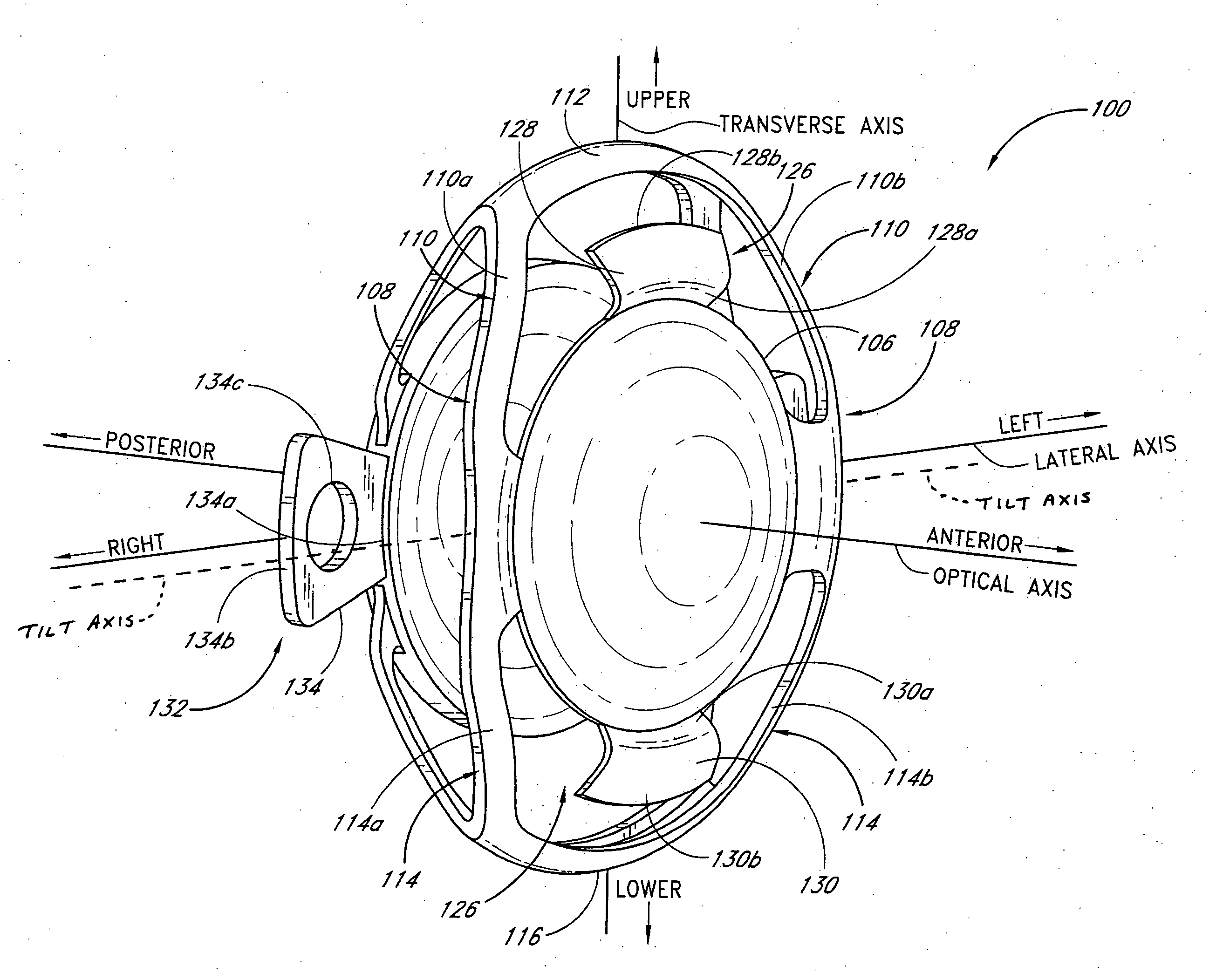
[0122]FIGS. 26-28 depict another embodiment 200 of the intraocular lens. It is contemplated that, except as noted below, this embodiment 200 may, in certain embodiments, be similar to any one or more of the embodiments disclosed in FIGS. 3-17 and FIGS. 21-25.

[0123] In the illustrated embodiment, the distance 202 between the free end 128b of the first retention member 128 and the free end 130b of the second retention member 130 preferably is between about 6 mm and about 8 mm. In one embodiment, the distance 202 preferably is between about 6.9 mm and about 7.3 mm.

[0124] In the illustrated embodiment, the distance 204 between the free end 134b of the first distending member 134 and the free end 136b of the second distending member 136 preferably is between about 8 mm and about 14 mm. In one embodiment, the distance 204 preferably is between about 9 mm and about 11 mm. In one embodiment, the distance 204 preferably is between about 9.7 mm and about 9.9 mm.

[0125] As shown in FIG. 28, t...

embodiment 300

[0126]FIGS. 29-31 depict another embodiment 300 of the intraocular lens. It is contemplated that, except as noted below, this embodiment 300 may, in certain embodiments, be similar to any one or more of the embodiments disclosed in FIGS. 3-17, FIGS. 21-25, and FIGS. 26-28.

[0127] In the illustrated embodiment, the distance 302 between the free end 128b of the first retention member 128 and the free end 130b of the second retention member 130 preferably is between about 6 mm and about 8 mm. In one embodiment, the distance 302 preferably is between about 6.9 mm and about 7.3 mm.

[0128] In the illustrated embodiment, the distance 304 between the free end 134b of the first distending member 134 and the free end 136b of the second distending member 136 preferably is between about 8 mm and about 14 mm. In one embodiment, the distance 304 preferably is between about 9 mm and about 11 mm. In one embodiment, the distance 304 preferably is between about 9.7 mm and about 9.9 mm.

[0129] As shown...

embodiment 400

[0130]FIGS. 32-37 depict another embodiment 400 of the intraocular lens. It is contemplated that, except as noted below, this embodiment 400 may, in certain embodiments, be similar to any one or more of the embodiments disclosed in FIGS. 3-17, FIGS. 21-25, FIGS. 26-28, and FIGS. 29-31.

[0131] In the illustrated embodiment, the distance 402 between the free end 128b of the first retention member 128 and the free end 130b of the second retention member 130 preferably is between about 6 mm and about 8 mm. In one embodiment, the distance 402 preferably is between about 6.9 mm and about 7.3 mm.

[0132] As best shown in FIGS. 32 and 35, the retention members 128, 130 are preferably provided with openings 416. Likewise, the transition members 138, 140 are preferably provided with openings 418. These openings 416, 418 preferably permit fluid to flow between the interior of the capsular bag 58 and the portions of the eye anterior of the bag 58 as discussed further below.

[0133] In the illustra...


PUM


Abstract

An accommodating intraocular lens implantable in an eye. The lens comprises an anterior portion having an anterior biasing element and an anterior optic having refractive power. The lens further comprises a posterior portion having a posterior biasing element and a posterior optic having refractive power. The anterior optic and the posterior optic are relatively moveable in response to action of the ciliary muscle to change the separation between the optics and the refractive power of the lens. The lens has an aberration-inducing force characteristic of about 70 mg to about 115 mg to allow aberration-inducing relative movement of the optics when the lens is in the eye, thereby adding optical aberration to the lens which increases depth of focus of the lens. In one variation, the lens has an aberration-inducing force characteristic of 70 mg to 115 mg. Related methods are also disclosed.

Description

RELATED APPLICATIONS [0001] This application is a continuation-in-part of U.S. patent application Ser. No. 10 / 207,717 (now U.S. patent application Publication No. US 2003 / 0078657 A1), filed Jul. 25, 2002, titled MATERIALS FOR USE IN ACCOMMODATING INTRAOCULAR LENS SYSTEM, which is a continuation-part of U.S. patent application Ser. No. 10 / 020,853 (now U.S. patent application Publication No. US 2002 / 0107568 A1), filed Dec. 11, 2001, titled ACCOMMODATING INTRAOCULAR LENS SYSTEM, which claims the benefit of U.S. Provisional Patent Applications No. 60 / 337,343, filed Nov. 9, 2001 and titled ACCOMMODATING INTRAOCULAR LENS SYSTEM; No. 60 / 283,856, filed Apr. 13, 2001 and titled ACCOMMODATING INTRAOCULAR LENS SYSTEM; and No. 60 / 264,179, filed Jan. 25, 2001 and titled ACCOMMODATING INTRAOCULAR LENS SYSTEM. This application is a continuation-part of U.S. patent application Ser. No. 10 / 017,920 (now U.S. patent application Publication No. US 2002 / 0116057 A1), filed Dec. 11, 2001, titled OPTIC CON...

Claims


Application Information

Patent Timeline
IPC IPC(8): A61F2/16
CPCA61F2/1613A61F2/1648A61F2/1629A61F2/1627A61F2/1632
Inventor NGUYEN, TUAN ANHZADNO-AZIZI, GHOLAM-REZAEVANS, SCOTTPORTNEY, VALEDMAR
Owner VISIOGEN
Why Eureka
Try Eureka