Method and apparatus for multi-level scan compression

a multi-level scan and compression technology, applied in the field of logic design and test using designfortest (dft) techniques, can solve the problems of significant computational overhead, linear equations that cannot be solved, and scan compression techniques utilizing sequential decompressors such as lfsr circuits are difficult to use, so as to achieve better balance scan chains

Inactive Publication Date: 2005-12-01
SYNTEST TECH
View PDF8 Cites 48 Cited by
  • Summary
  • Abstract
  • Description
  • Claims
  • Application Information

AI Technical Summary

Benefits of technology

[0016] The main advantage of this technique is that since the decompressor and compressor are now split, it is possible to perform scan compression and where only one level of logic exists between any two scan cells, by dividing the long path between the compressed scan inputs (or outputs) and the internal scan chains over two or more decompressors (or compressors). This allows us to perform compressed scan at a similar speed as regular scan. A further advantage is that it allows us to better balance scan chains, by performing the scan decompression and compression at different lengths for different scan chains. This allows us to control all scan chains to be the same length regardless of the number of scan cells controlled by each compressed scan input.

Problems solved by technology

In general, scan compression techniques utilizing a sequential decompressor such as an LFSR circuit are difficult to use, requiring additional software to solve the linear equations involved in order to translate the decompressed scan data patterns into the external compressed scan data patterns that can be used to generate the required decompressed scan data patterns through the LFSR.
In some cases, these linear equations can turn out to be unsolvable, requiring multiple iterative runs where the decompressed scan data patterns are reordered, duplicated, or regenerated in order to be able to generate compressed scan data patterns which covers all the required faults.
This can result in a significant computational overhead.
In general, the compression capability of these techniques is limited since it requires that the decompressed scan data patterns be generated loosely in order to guarantee that the compression equations can be solved.
This results in compressing decompressed scan data patterns that are sub-optimal, as opposed to compressing tightly packed decompressed scan data patterns where both static and dynamic compaction are performed aggressively.
This makes these techniques much less attractive than techniques utilizing a combinational decompressor, built mainly out of XOR or MUX gates.
The main difficulty with current decompression solutions utilizing a combinational decompressor is that the decompression is typically done in one stage, which is placed between the compressed scan inputs and the first scan cell of each internal scan chains.
An additional delay is further introduced due to the fact that the first scan cell is typically located at a distance from the compressed scan inputs.
Finally, since the compressed scan inputs are typically shared in normal mode, this can result in overloading the input pins and reducing the amount of time these pins can be operated at, which can adversely affect the regular chip functionality.
The same problems exist in combinational decompressors utilizing MUX gates as their basic building block.
A similar problem exists when the scan data responses captured in the internal scan chains are compressed into compressed scan data responses driven out on a smaller number of compressed scan outputs.
For compression techniques utilizing a sequential compressor, difficulties arise due to the fact that all unknowns now have to be accounted for and tolerated in scan mode (during shift-in and shift-out operations), which can result in a significant gate overhead for scan designs utilizing these techniques.
For designs utilizing a combinational compressor, a similar number of XOR gate levels may have to be placed between the last scan cell of the internal scan chains and the compressed scan outputs, creating similar delays and loading problems as the combinational decompressor used on the input side.
The same problems also exist in combinational compressor designs utilizing MUX gates as their basic building block.

Method used


Image

  • Method and apparatus for multi-level scan compression
  • Method and apparatus for multi-level scan compression
  • Method and apparatus for multi-level scan compression

Examples


first embodiment

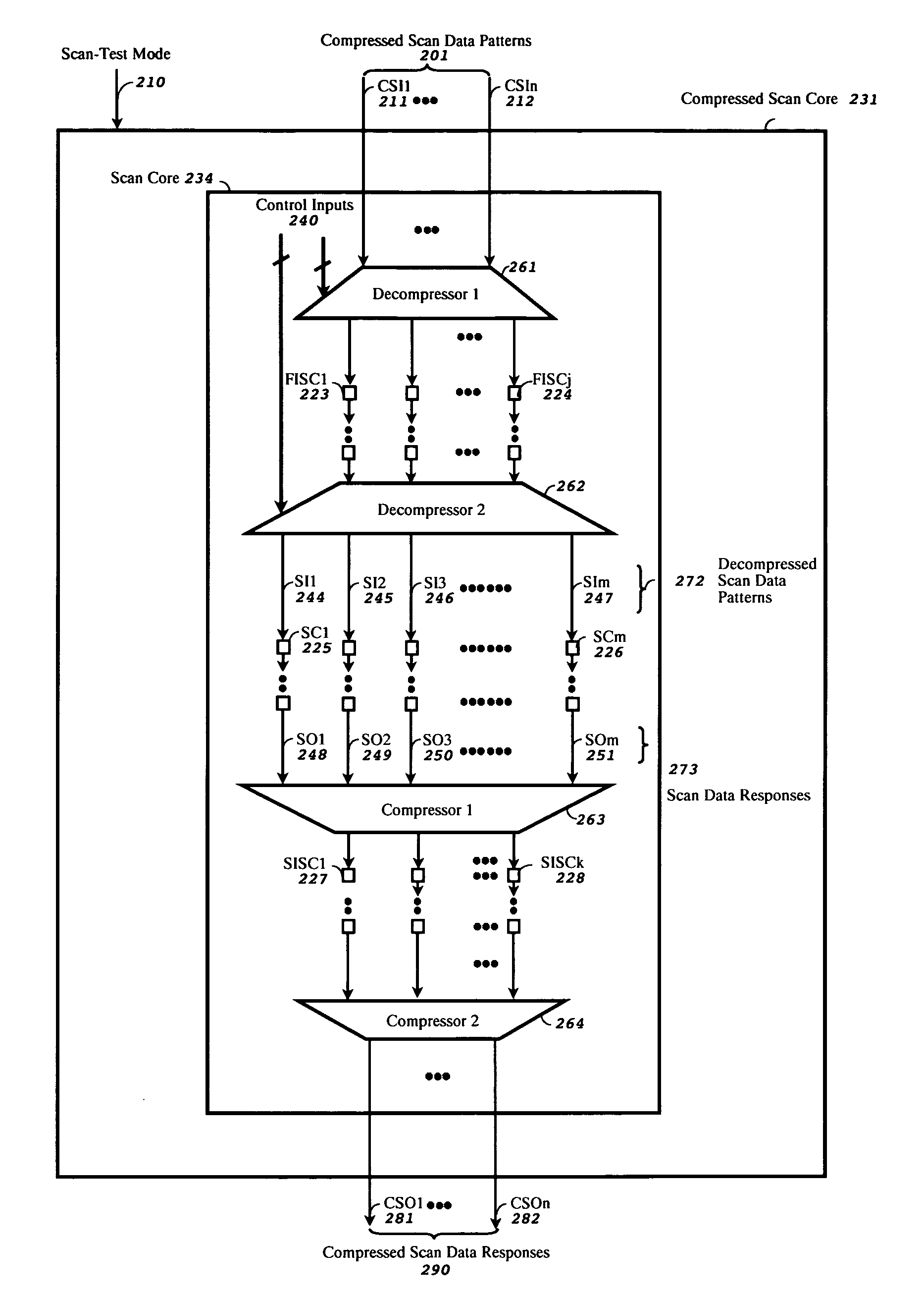
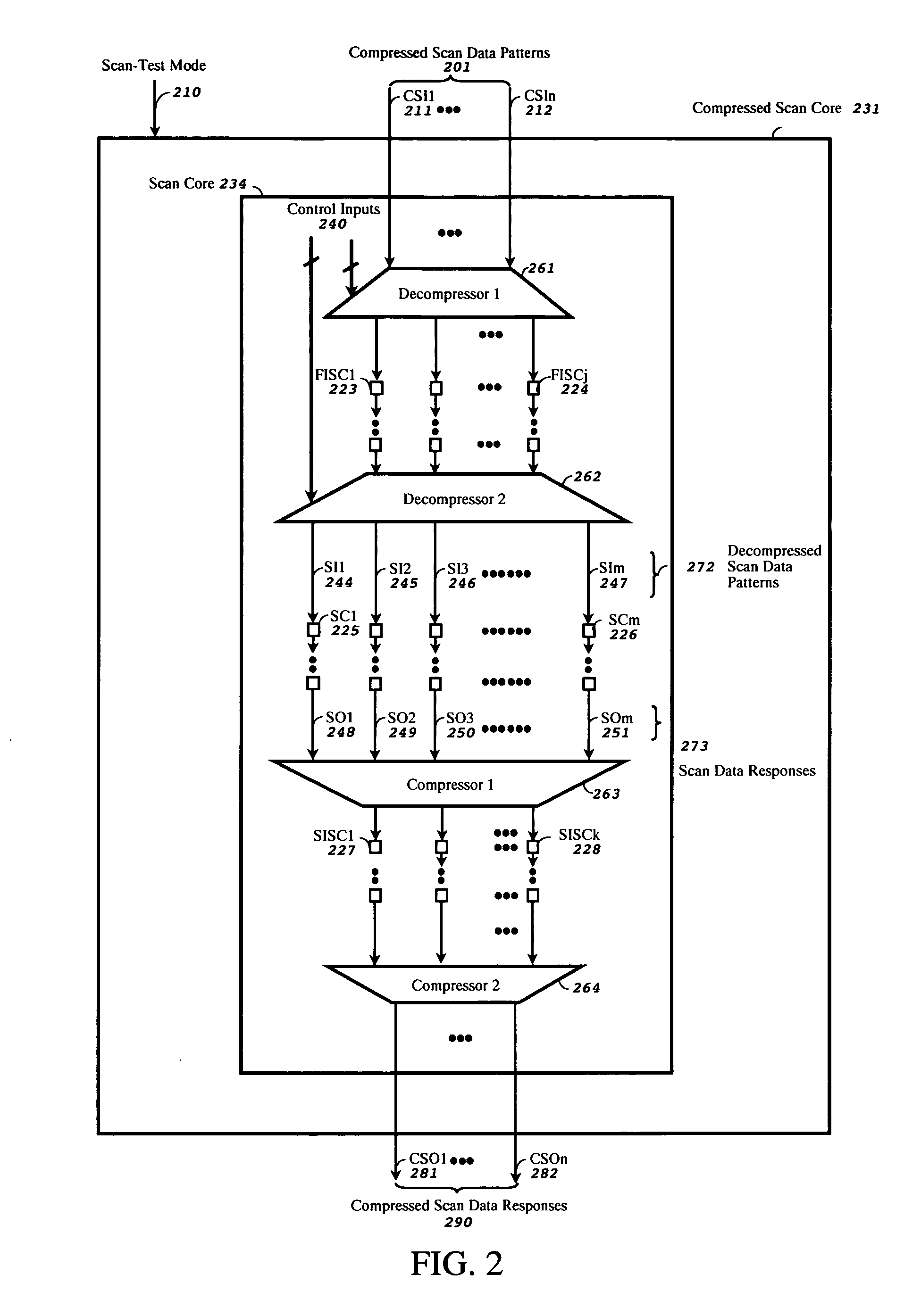
[0028]FIG. 2 shows a multi-level compressed scan test system, in accordance with the present invention, for testing scan-based integrated circuits. The Compressed Scan Core 231 comprises a Scan Core 234 with two decompressors Decompressor1261 and Decompressor2262 and two compressors Compressor1263 and Compressor2264 embedded in the Scan Core 234. The Scan Core 234 also comprises J First Intermediate Scan Chains FISC1223 to FISCj 224 embedded between Decompressor1261 and Decompressor2262, K Second Intermediate Scan Chains SISC1227 to SISCk 228 embedded between Compressor1263 and Compressor2264, and M scan chains SC1225 to SCm 226.

[0029] The Compressed Scan Core 231 further accepts a Scan-Test Mode 210 signal, and Compressed Scan Data Patterns 201 applied on external compressed scan inputs CSI1211 to CSIn 212 to drive the inputs of the first decompressor Decompressor1261, which also accepts Control Inputs 240 to control the Decompressor1261 during scan-test. The Decompressor1261 reads...

second embodiment

[0033]FIG. 4 shows a multi-level decompressor, in accordance with the present invention. The Decompressor 402 accepts Compressed Scan Data Patterns 401 and Control Inputs 404 to generate Decompressed Scan Data Patterns 403 by utilizing exclusive-OR (XOR) gates 405. The optional Control Inputs 404 are used to alter the relationship for different scan patterns, in order to improve fault coverage and fault diagnosis.

third embodiment

[0034]FIG. 5 shows a multi-level decompressor, in accordance with the present invention. The Decompressor 502 accepts Compressed Scan Data Patterns 501 and Control Inputs 504 to generate Decompressed Scan Data Patterns 503 by utilizing multiplexor (MUX) gates 505. The optional Control Inputs 504 are used to alter the relationship for different scan patterns, in order to improve fault coverage and fault diagnosis.

[0035]FIG. 6 shows a first embodiment of a multi-level compressor, in accordance with the present invention. The Compressor 602 accepts Scan Data Responses 601 to generate Compressed Scan Data Responses 603, by utilizing exclusive-OR (XOR) gates 604. A compressor utilizing an X-tolerant XOR network, having at least one internal scan chain output connected to two or more XOR gates, is also included within the scope of this invention.

[0036]FIG. 7 shows a flow diagram of a method for synthesizing two or more decompressors in either RTL (register-transfer level) or gate-level, ...


PUM


Abstract

A multi-level scan compression method and apparatus for reducing test data volume and test application time in a scan-based integrated circuit without reducing the speed of the scan chain operation in scan-test mode or self-test mode. The scan-based integrated circuit contains one or more scan chains, each scan chain comprising one or more scan cells coupled in series. The method and apparatus comprises two or more decompressors embedded between N compressed scan inputs and M scan chains, where N<M, to broadcast compressed scan data patterns driven through the N compressed scan inputs into decompressed scan data patterns stored in the M scan chains. The multi-level scan compression approach allows us to speed up the shift-in / shift-out operation during decompression using two or more decompressors separated by intermediate scan chains. The method and apparatus further comprises two or more compressors separated by intermediate scan chains to speed up the shift-in / shift-out operation during compression.

Description

RELATED APPLICATION DATA [0001] This application claims the benefit of U.S. Provisional Application No. 60 / 574,200 filed May 26, 2004.FIELD OF THE INVENTION [0002] The present invention generally relates to the field of logic design and test using design-for-test (DFT) techniques. Specifically, the present invention relates to the field of logic test and diagnosis for integrated circuits using scan or built-in self-test (BIST) techniques. BACKGROUND [0003] Different scan compression techniques have emerged for compressing scan data patterns, generated using automatic test-pattern generation (ATPG) tools, for reducing both test application time and test data volume. Current scan compression techniques rely on inserting a decompressor between a limited number of compressed scan inputs and a large number of internal scan chains. The decompressor can be designed as a combinational circuit that generates decompressed scan data patterns for the internal scan chains depending on the compre...

Claims


Application Information

Patent Timeline
Patent Type & Authority Applications(United States)
IPC IPC(8): G01R31/28G01R31/3185
CPCG01R31/318547
Inventor ABDEL-HAFEZ, KHADER S.WU, SHIANLING
Owner SYNTEST TECH
Why Eureka
Try Eureka