
Thermostatic valve for a cooling system of an internal combustion engine

a technology of internal combustion engine and thermostatic valve, which is applied in the direction of engine cooling apparatus, combustion engine, machines/engines, etc., can solve the problems of high cost of such a rotary slide thermostatic valve, in particular for controlling it, and disadvantages such as its heavy weight and large size, and achieves shorter switching times and more precise control of the switched states

Inactive Publication Date: 2005-12-08
DAIMLER AG
View PDF3 Cites 20 Cited by
  • Summary
  • Abstract
  • Description
  • Claims
  • Application Information

AI Technical Summary

Benefits of technology

[0018] With this thermostatic valve it is possible to reset the switched states of a rotary slide thermostatic valve described at the beginning, and even the switched state of full throttle in the preferred embodiments of the invention. By providing the thermostatic valve with a wax cartridge thermostat it is possible to implement a more cost-effective design with a smaller size and a lower weight than with a rotary slide thermostatic valve. Since the temperature acting on the wax cartridge thermostat can be increased by the electric heating element, the switched state of the thermostatic valve can be set more quickly and at a lower coolant temperature. This is advantageous in particular where there are sudden load changes of the internal combustion engine which would otherwise give rise to an excessively large increase in the temperature of the coolant.
[0020] In a refinement of the invention, the thermostatic valve is also provided with a coolant bypass passage between the inlet connection and the second outlet connection of the coolant bypass line. This measure ensures that the wax cartridge thermostat of the thermostatic valve of the invention is continuously contacted by the coolant irrespective of the switched state of the thermostatic valve, therefore permitting more precise control of the switched states with shorter switching times.

Problems solved by technology

The high costs of such a rotary slide thermostatic valve, in particular for controlling it, as well as its heavy weight and its large size are disadvantageous.

Method used


Image

  • Thermostatic valve for a cooling system of an internal combustion engine
  • Thermostatic valve for a cooling system of an internal combustion engine
  • Thermostatic valve for a cooling system of an internal combustion engine

Examples


Embodiment Construction

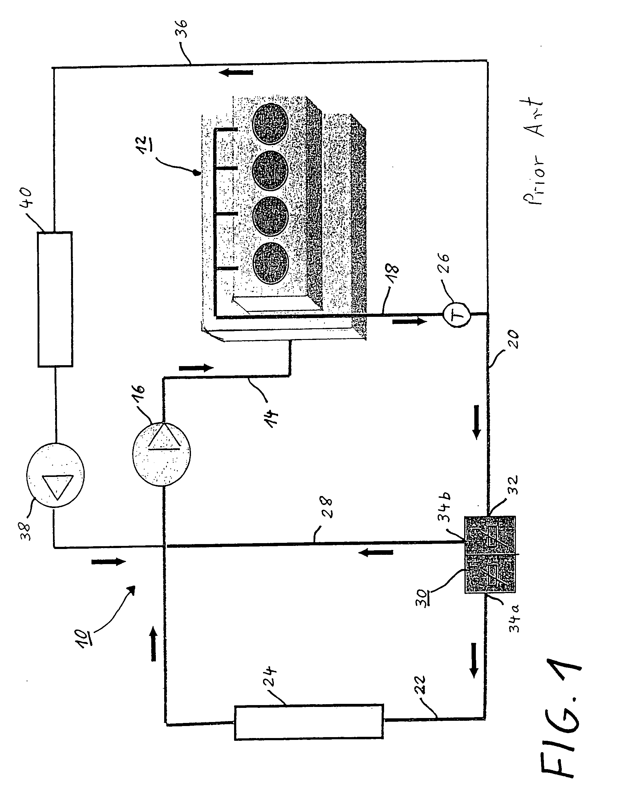
[0040] Various exemplary embodiments of a thermostatic valve according to the present invention and their methods of operation will be explained in more detail below with reference to FIGS. 3 to 9. The thermostatic valves can all be used in a coolant circuit such as has been described with reference to FIG. 1, or a similar cooling system of internal combustion engines. The cooling system in FIG. 1 will not be described once more in order to avoid unnecessary repetitions at this point. Similar or correspondingly acting components have been labeled with the same reference numbers in all the figures.

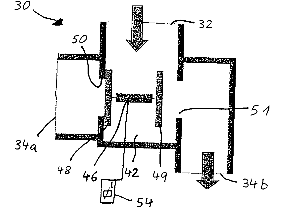
[0041] The thermostatic valve 30 according to the first exemplary embodiment which is illustrated in FIG. 3 contains a valve chamber 42 which can be connected to the coolant return line 20 via an inlet connection 32 (see FIG. 1), to the coolant radiator line 22 via a first outlet connection 34a, and to the coolant bypass line 28 via a second outlet connection 34b. A wax cartridge thermosta...


PUM


Abstract

In a thermostatic valve for a cooling system of an internal combustion engine with an inlet connection, a first outlet connection and a second outlet connection, and first, second and third valve elements for closing and opening the inlet and first and second outlet connections, at least two wax cartridge thermostats are provided for operating the valve elements and at least one of the wax cartridge thermostats is connected to an electric heating element for influencing the operation of the respective wax thermostat.

Description

[0001] This is a Continuation-in-Part Application of International Application PCT / EP2003 / 011521 filed Oct. 17, 2003 and claiming the priority of German application 102 53 469.1 filed Nov. 16, 2002.BACKGROUND OF THE INVENTION [0002] The invention relates to a thermostatic valve for a cooling system of an internal combustion engine, in particular of an internal combustion engine of a motor vehicle. [0003] A cooling system for an internal combustion engine usually comprises a coolant circuit 10 in which the present invention can also be used and which is schematically illustrated in FIG. 1. [0004] The coolant, for example water, is fed to the internal combustion engine 12 via a coolant feed line 14 by means of a pump 16. After the coolant has passed through the internal combustion engine 12 and correspondingly has been heated up owing to an exchange of heat, it flows via a coolant discharge line 18, a coolant return line 20 and a coolant radiator line 22 to a radiator 24 in order to b...

Claims


Application Information

Patent Timeline
Patent Type & Authority Applications(United States)
IPC IPC(8): F01P7/16
CPCF01P7/16F01P7/167Y02T10/146F02B29/0475F02B29/0493F01P2070/04Y02T10/12
Inventor FINKBEINER, HANSJORGGELLNER, HARALDHOLLANDER, TELSE
Owner DAIMLER AG
Features
  • Generate Ideas
  • Intellectual Property
  • Life Sciences
  • Materials
  • Tech Scout
  • Unparalleled Data Quality
  • Higher Quality Content
  • 60% Fewer Hallucinations
Learn More