
Steam valve

Active Publication Date: 2005-12-08
KK TOSHIBA +1
View PDF6 Cites 11 Cited by
  • Summary
  • Abstract
  • Description
  • Claims
  • Application Information

AI Technical Summary

Benefits of technology

[0083] a bulkhead provided between the strainer and the valve casing to prevent a collision of the two main steam flows having been separated by and flowing around from the closing portion.
[0092] a bulkhead provided between the strainer and the valve casing to prevent a collision of the two main steam flows having been separated by and flowing around from the closing portion.
[0101] a bulkhead provided between the strainer and the valve casing to prevent a collision of the two main steam flows having been separated by and flowing around from the closing portion; and
[0107] a bulkhead provided between the strainer and the valve casing to prevent a collision of the two main steam flows having been separated by and flowing around from the closing portion.
[0121] a bulkhead provided between the strainer and the valve casing to prevent a collision of the two main steam flows having been separated by and flowing around from the closing portion; and
[0126] According to the steam valve of the present invention provided with the above-described structures and characteristics, a device for blocking a part of the main steam flow is included in the strainer where the main steam flows from outside of the strainer to inside thereof, and the device for blocking the part of the main steam flow is disposed at an appropriate position in the strainer. Accordingly, the other main steam is prevented from flowing into the area where the deficiency of the speed of secondary flow based on the drift of the main steam that flows from outside of the strainer to inside thereof exists, and the pressure loss due to the swirling flow of the main steam can be further decreased.

Problems solved by technology

However, because both the size of the main steam shut-off valve and the size of the steam control valve (steam flow regulation valve) are extremely large, a large space for installing the main steam shut-off valve and the steam control valve (steam flow regulation valve) has been required.
On the other hand, the steam valve 1 provides a number of problems, and one of the problems is a reduction of a pressure loss.
Thus, the pressure loss has been further increased due to the swirling flow.
Then, two steam jets join together at an outlet side of the strainer 8 and collide with each other, resulting in the occurrence of a large mixing loss.
Thus, with the known steam valve of the combined type, it is difficult to suppress the pressure loss caused by factors such as the secondary flow, the mixing loss, or the like.

Method used


Image

  • Steam valve
  • Steam valve
  • Steam valve

Examples


first embodiment

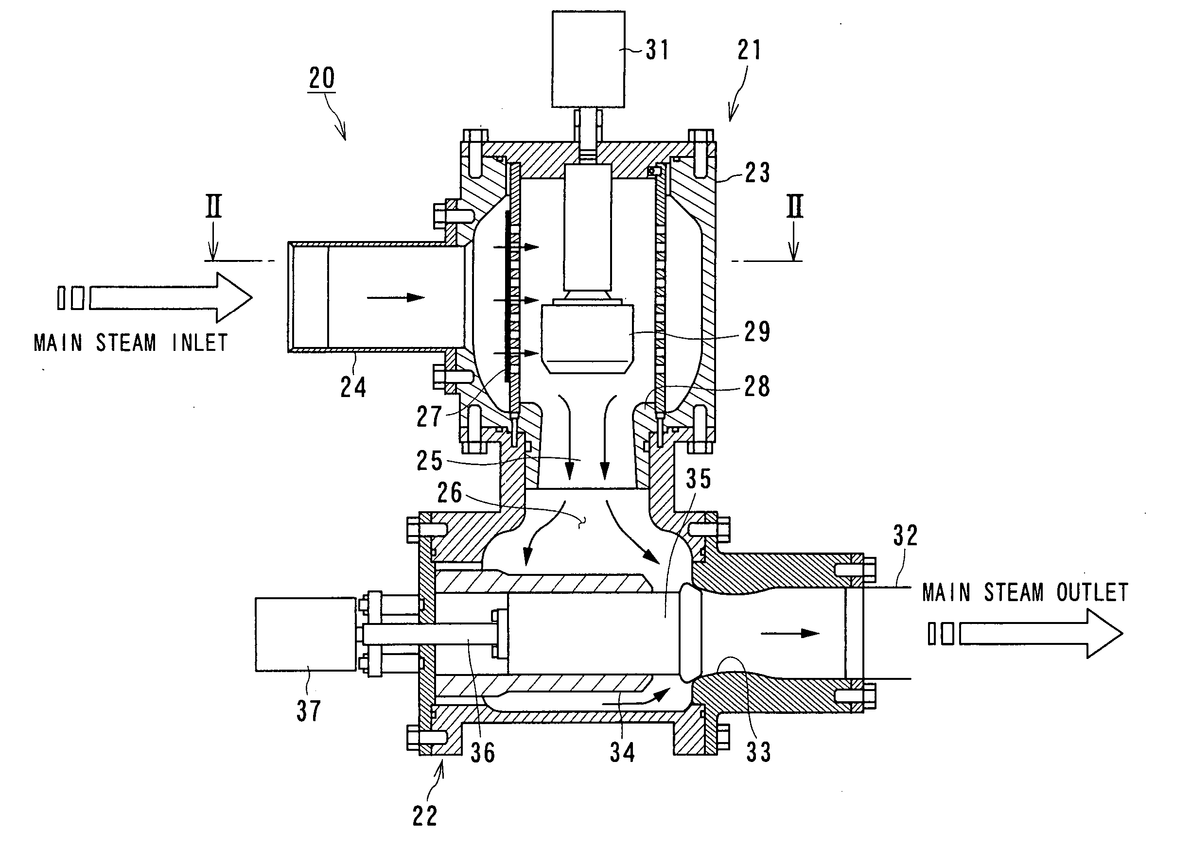
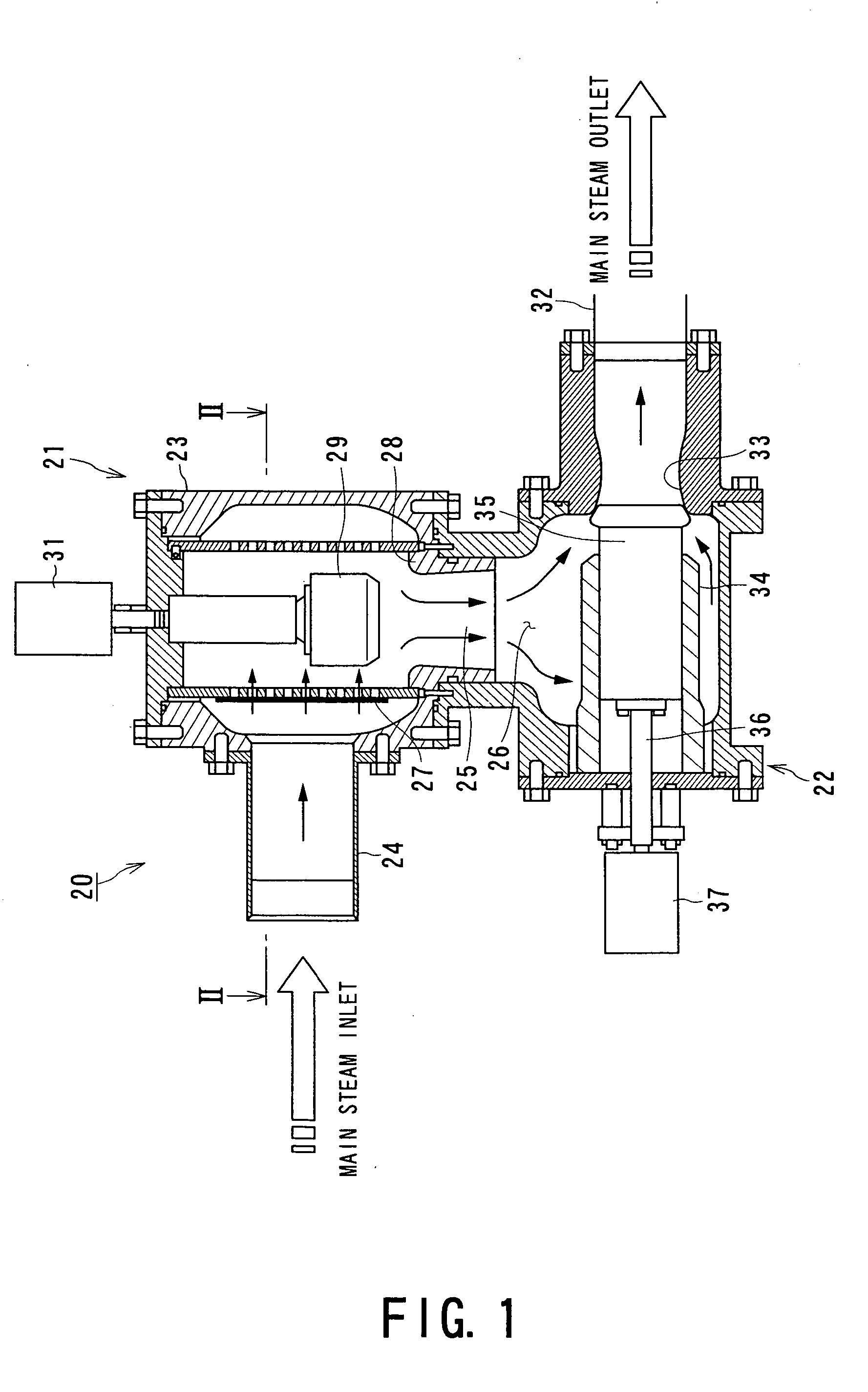
[0160]FIG. 1 shows the steam valve in accordance with the present invention.

[0161] A steam valve 20 with respect to the first embodiment is composed of a main steam shut-off valve and a steam control valve (steam flow regulation valve) combined with each other, in which a first valve device 21 that corresponds to the main steam shut-off valve is disposed at an upstream side and a second valve device 22 that corresponds to the steam control valve (steam flow regulation valve) is disposed at a downstream side of the main steam, and in addition, the first valve device 21 and the second valve device 22 are housed in one valve casing 23.

[0162] The first valve device 21 is provided with a first main steam inlet 24 in the valve casing 23 and a first main steam outlet 25 that is connected to a second main steam inlet 26 of the second valve device 22, and houses therein a strainer 27 for removing impurities such as oxidized scale and the like.

[0163] Further, the first valve device 21 is pr...

fifth embodiment

[0174]FIGS. 6 and 7 are conceptual diagram showing the steam valve with respect to the present invention.

[0175] In addition, FIG. 6 is a vertical cross-sectional diagram showing the steam valve in accordance with the present invention and FIG. 7 is a cutaway cross-sectional diagram of FIG. 6 looking from the direction of arrows VII-VII.

[0176] Further, the same reference numerals designate corresponding constituent elements in the first embodiment.

[0177] The steam valve 20 with respect to the present fifth embodiment is composed of the valve casing 23 respectively provided with the main steam inlet 45 at one side and the main steam outlet 46 provided in parallel with the main steam inlet 45 at another side, i.e., the opposite side, the strainer 27 formed of, for example, the cylindrically shaped cylindrical element 38 having a plurality of tiny passing-through holes 40, the valve body 48 that detachably contacts the valve seat 47, and the valve rod 50 driving the valve body 48 to f...

sixth embodiment

[0180] Further, in the present embodiment, the closing portions 51a and 51b are disposed in a direction orthogonally crossing the axial line of each of the main steam inlet 45 and the main steam outlet 46. However, without being limited to the present embodiment, for example, interrupting plates 52a and 52b that close a part of the passing-through holes 40 of the strainer 27 may be disposed at a position orthogonally crossing an axial line of each of the main steam inlet 45 and the main steam outlet 46 and outside of the strainer 27, instead of the closing portions 51a and 51b, as shown in the sixth embodiment in FIG. 8.

[0181]FIG. 9 is a conceptual diagram showing the steam valve with respect to seventh embodiment in accordance with the present invention. FIG. 9A in FIG. 9 is a conceptual plan view showing the steam valve when the closing plate mounted on the strainer is moved to a position facing the main steam inlet in an unsteady operation, and FIG. 9B is a conceptual plan view s...


PUM


Abstract

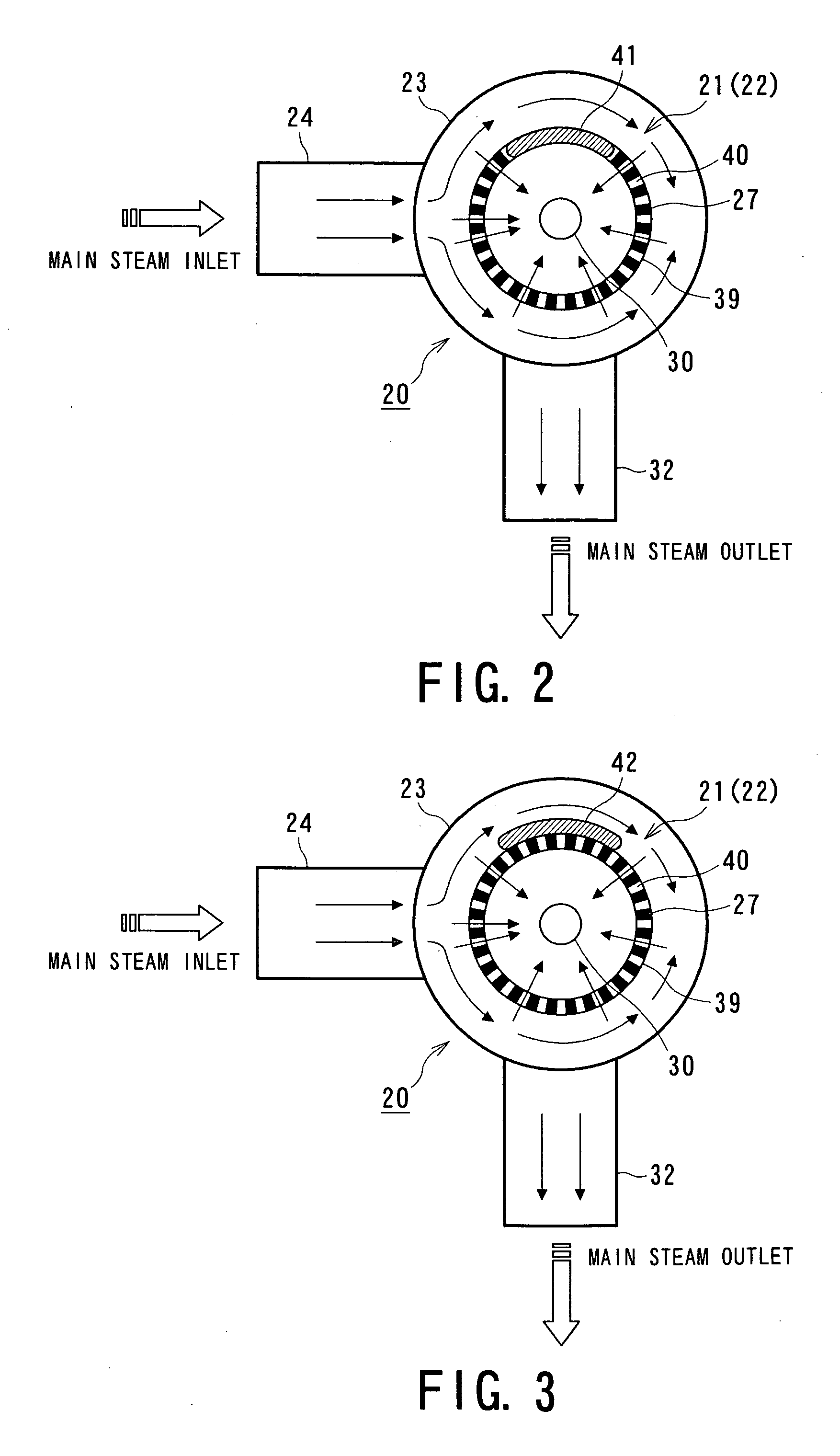
A steam valve in accordance with the present invention is the steam valve that houses a first valve device 21 composed of a valve seat, a valve body, a valve rod, and a driving device, and a second valve device 22 composed of the valve seat, the valve body, the valve rod, and the driving device, combined with each other in the valve casing 23, and a closing portion 41 to block a part of a main steam flow flowing from outside to inside of a strainer is formed in the strainer 27 that is housed in the valve casing 23 and that surrounds the valve body 29 of the first valve device. According to the above described configuration, the steam valve that is aimed to further decrease a pressure loss can be provided by effectively controlling the steam flow in the strainer housed in the valve casing.

Description

Technical Field [0001] The present invention relates to a steam valve applied to a steam turbine plant, and more particularly, relates to an improvement in a steam valve in which a main steam shut-off valve and a steam control valve (steam flow regulation valve) are combined. BACKGROUND ART [0002] In general, there are many steam turbine plants having so-called three-casing axial-flow type structures in which a high pressure steam turbine, an intermediate pressure steam turbine, and a low pressure steam turbine are directly connected to a shaft of a turbine rotor so that a power generator generates as much load (output) as possible. [0003] The steam turbine plant having the three-casing axial-flow type structure is configured to house a plurality of turbine stages, in which a turbine nozzle and a turbine blade are combined in a turbine casing of each of the high pressure steam turbine, the intermediate pressure steam turbine, and the low pressure steam turbine, along an axial direct...

Claims


Application Information

Patent Timeline
IPC IPC(8): F01D17/14F16K47/08
CPCF16K47/08F01D17/145Y10T137/7976Y10T137/8085Y10T137/86734Y10T137/87917Y10T137/87925F01D17/10F16K31/44
Inventor OOTOMO, FUMIOOOISHI, TSUTOMUNIIZEKI, YOSHIKIFUKUYAMA, YOSHITAKAMATSUDA, HISASHISHINDO, OSAMU
Owner KK TOSHIBA
Learn More