
Double tube

Active Publication Date: 2018-02-22
FURUKAWA ELECTRIC CO LTD
View PDF5 Cites 0 Cited by
  • Summary
  • Abstract
  • Description
  • Claims
  • Application Information

AI Technical Summary

Benefits of technology

The present invention provides a double tube that can prevent buckling and flattening of the inner tube when bending is performed. This is achieved by facilitating bending of the inner tube, decreasing pressure loss, and preventing stagnation of the internal fluid. Additionally, bending of the outer tube with the repetitive bending diameter or more ensures a reliable prevention of buckling and flattening of the inner tube. The long heat transmission path between the outer tube and the inner tube can be ensured, and heat penetration to the inner tube from the outer tube can be decreased. The heat insulating material provided on the outer periphery of the terminal member and the outer tube can be finished to be smooth, and in addition, shifting of the heat insulating material can be prevented.

Problems solved by technology

However, in the art of Japanese Patent Laid-Open No. 2000-120940, the inner tube is constituted of a flat tube, and therefore it is difficult to bend, and when bending is performed when the vacuum insulated tube is laid, the state of the inner tube cannot be confirmed from outside, so that Japanese Patent Laid-Open No. 2000-120940 has the problem that even if the outer tube can be properly bent, buckling and flattening of the inner tube is likely to be caused.
Further, in the art of Japanese Patent Laid-Open No. 08-208872, the foamed body is formed from a resin, and therefore has the problem of deteriorating by use for a long time period, and decreasing heat insulation performance.
Further, the foamed body has low strength, and therefore has the problem that flaws and dents are easily generated and this leads to a decrease in heat insulation performance.

Method used


Image

  • Double tube
  • Double tube
  • Double tube

Examples


first embodiment

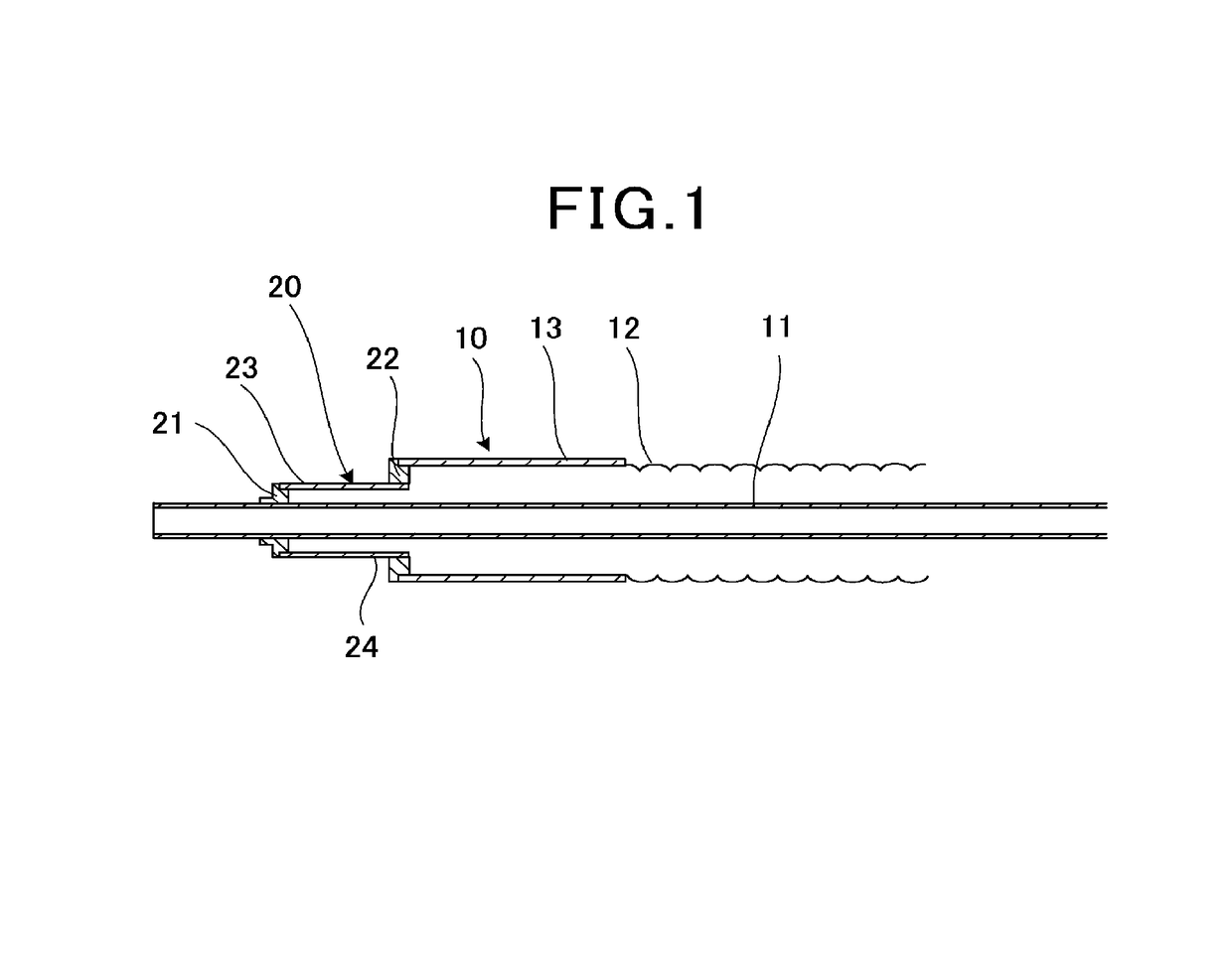
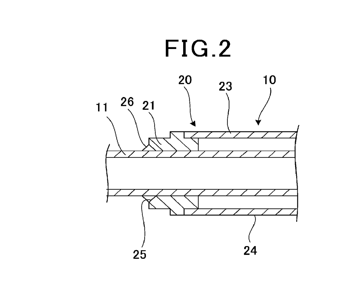
[0047]FIG. 1 is a schematic perspective view illustrating a double tube according to the present invention. FIG. 2 is an enlarged view of an inner tube end portion in FIG. 1. Note that in the present embodiment, an example of a case in which a vacuum insulated tube is applied as a double tube is described.

[0048]In the present embodiment, a vacuum insulated tube 10 is constituted of a double tube formed of an inner tube 11 and an outer tube 12. The inner tube 11 is constituted of a flat tube of brass or pure copper capable of being bent, for example. Here, the reason why the copper tube is used is that the copper tube has corrosion resistance, is easily plumbed, is light, has a smooth inner surface and has small friction resistance, and therefore less scale is attached during use, so that pressure loss decreases.

[0049]As a kind of copper, brass and pure copper are favorable, and pure copper with low possibility of a dezincing phenomenon and stress corrosion cracking is more preferabl...

second embodiment

[0088]the present invention will be described next.

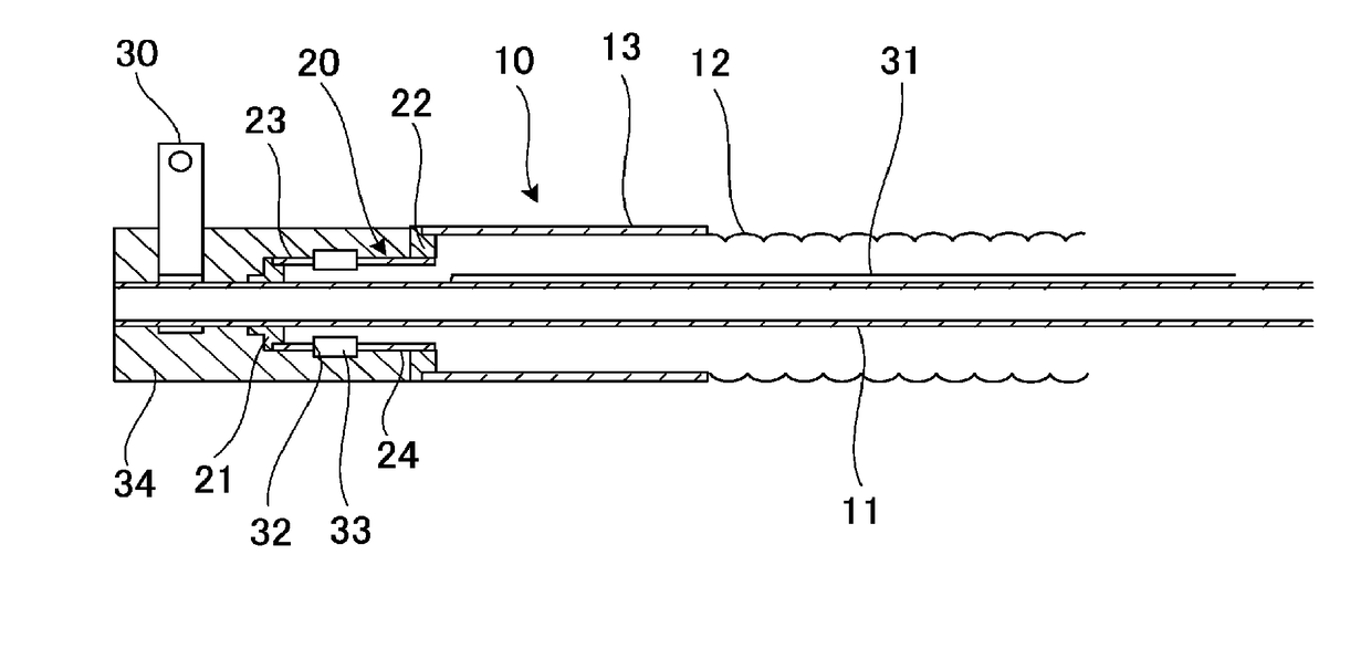
[0089]FIG. 6 is a schematic configuration view illustrating the second embodiment of the present invention.

[0090]In the present embodiment, a current terminal 30 is connected to at least one of both end portions of the inner tube 11. Further, in the present embodiment, a superconducting wire 31 is wound on the outer periphery of the inner tube 11. Note that a metal (not illustrated) is wound on the outer periphery of the inner tube 11, and the superconducting wire 31 may be wound on the outer periphery of the metal.

[0091]Further, in the intermediate cylinder portion 23 of the terminal member 20, an insulating slit 32 is continuously formed in a circumferential direction, and a ring-shaped insulating member 33 is provided in the insulating slit 32. The insulating member 33 is configured to electrically insulate the inner tube 11 and the outer tube 12.

[0092]Further, the heat insulating material 34 is provided on the outer peripheral p...


PUM


Abstract

A double tube is provided, which can reliably prevent buckling and flattening of an inner tube even when bending is performed.

Description

BACKGROUND OF THE INVENTIONField of the Invention[0001]The present invention relates to a double tube, and particularly relates to a double tube that has a double tube structure of an inner tube and an outer tube, and holds a space between the inner tube and the outer tube in vacuum.Description of the Related Art[0002]In general, as the insulating methods of insulated tubes, there are mainly two kinds that are a non-vacuum insulated tube and a vacuum insulated tube. A non-vacuum insulated tube is such that a tube is covered with a heat insulating material for cold reservation such as urethane foam, and non-vacuum insulated tubes are widely used as tubes for LNG, liquid oxygen and liquid nitrogen.[0003]As a vacuum insulated tube, multilayer heat insulation and powder vacuum heat insulation are well known. Multilayer heat insulation is such that what is made by laminating an aluminum deposition film in layer and called super insulation is sealed, and is decompressed to high vacuum. Fu...

Claims


Application Information

Patent Timeline
IPC IPC(8): F16L59/075F16L59/065F16L9/02F16L57/02H01B12/16
CPCF16L59/075F16L59/065F16L9/02F16L57/02H01B12/16F16L59/141F16L59/143Y02E40/60
Inventor YAGI, MASASHIFUKUSHIMA, HIROYUKITAKAGI, TOMOHIROFURUKAWA, MAKOTO
Owner FURUKAWA ELECTRIC CO LTD
Learn More