Refrigeration apparatus

Active Publication Date: 2009-06-04
SANYO ELECTRIC CO LTD
View PDF2 Cites 4 Cited by
  • Summary
  • Abstract
  • Description
  • Claims
  • Application Information

AI Technical Summary

Benefits of technology

[0030]In consequence, the heat exchange between the refrigerants having the flow rate corresponding to the number of the cooling units to be connected can be performed in each internal heat exchanger of the internal heat exchanger unit. Therefore, while decreasing the pressure loss of the refrigerant circulated through the internal heat exchanger, the heat exchange between the refrigerant discharged from the radiator and the refrigerant discharged from the evaporator can be performed. The temperature of the refrigerant flowing from the radiator into the pressure reducing unit can efficiently be lowered to enlarge the entropy difference between the evaporators, thereby improving the refrigeration capability.
[0031]Consequently, the compressor can be prevented from being damaged by the liquid compression, without providing any accumulator.
[0032]According to the sixth aspect of the invention, in the above inventions, the double tube constituting the internal heat exchanger is constituted of the inner tube and the outer tube, the high pressure side flow path through which the refrigerant from the radiator flows is constituted in the inner tube, and the low pressure side flow path through whic

Problems solved by technology

In consequence, the enlargement of an installation space or the lowering of the refrigeration capability in the evaporator is incurred.
However, such an internal heat exchanger is installed together with the compressor and the radiator in a refrigerator-side unit,

Method used


Image

  • Refrigeration apparatus
  • Refrigeration apparatus
  • Refrigeration apparatus

Examples


Example

Embodiment 1

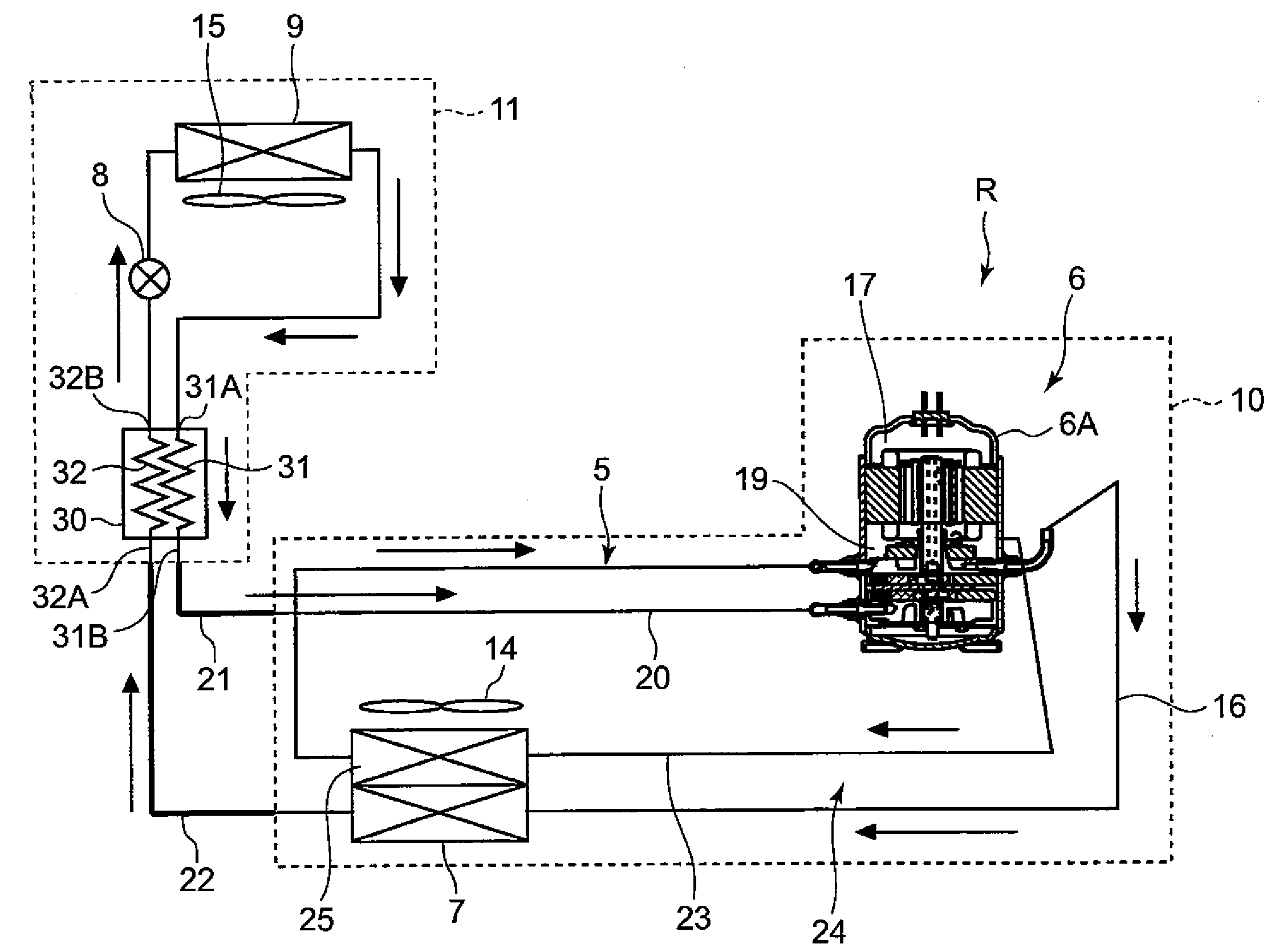
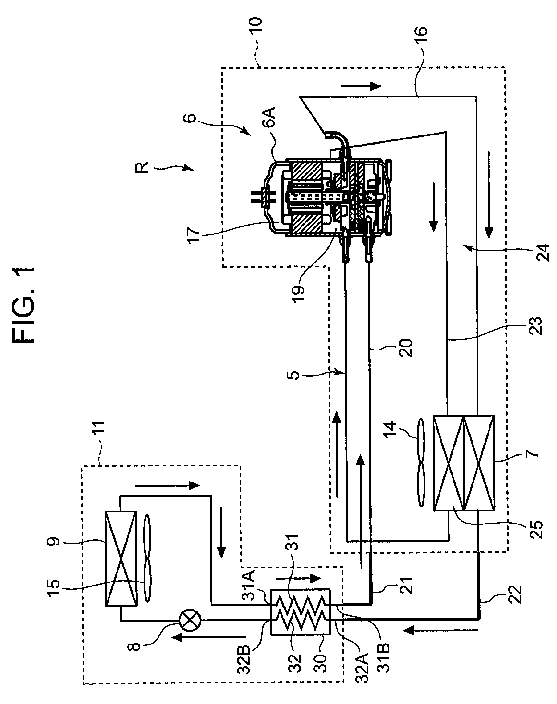
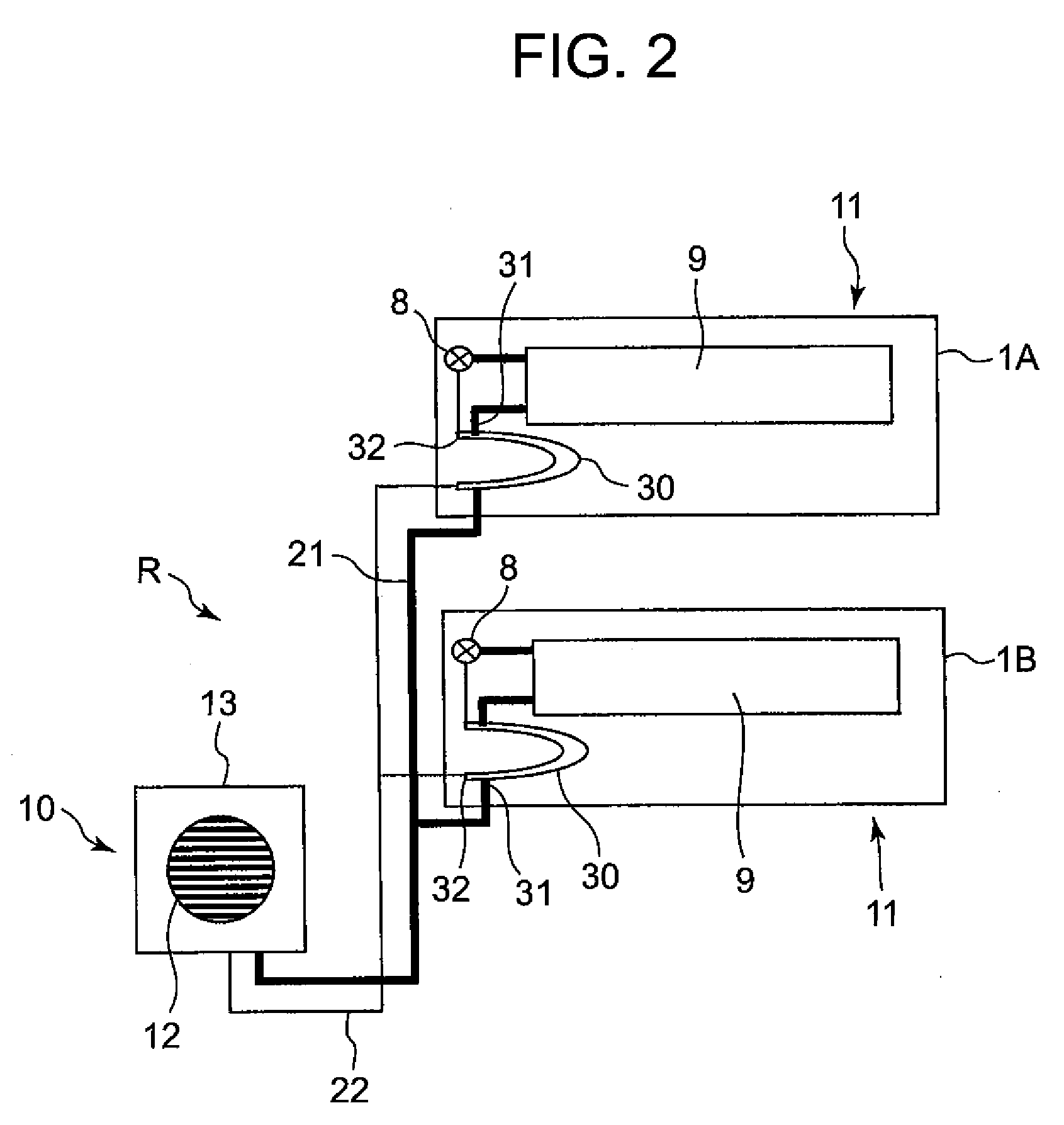
[0044]First, a refrigeration apparatus R as Embodiment 1 will be described with reference to FIGS. 1 to 3. FIG. 1 shows a refrigerant circuit diagram of one embodiment of a refrigeration apparatus of the present invention, FIG. 2 shows a schematic refrigerant circuit diagram showing a state in which the apparatus is installed in a showcase, and FIG. 3 shows a perspective view of an internal heat exchanger, respectively.

[0045]The refrigeration apparatus R of the present embodiment is used for cooling a plurality of showcases 1 . . . installed in a store such as a supermarket or a convenience store. FIG. 2 shows the apparatus for cooling two showcases 1A, 1B.

[0046]In FIG. 1, reference numeral 5 is a refrigerant circuit of the refrigeration apparatus R, and the circuit is constituted by annularly connecting a compressor 6, a radiator 7, an electronic expansion valve 8 as a pressure reducing unit, an evaporator 9 and the like to one another.

[0047]The compressor 6, the radiat...

Example

Embodiment 2

[0083]Next, a refrigeration apparatus S as Embodiment 2 will be described with reference to FIGS. 4 and 5. FIG. 4 shows a refrigerant circuit diagram of the refrigeration apparatus S, and FIG. 5 shows a schematic refrigerant circuit diagram to which the refrigeration apparatus S is applied, respectively. It is to be noted that in the drawings, components denoted with the same reference numerals as those of FIGS. 1 to 3 have the same constitution and produce the same effects, and hence the description thereof is omitted.

[0084]The refrigeration apparatus S of Embodiment 2 is used for cooling a plurality of showcases 2 . . . installed in a store such as a supermarket or a convenience store in the same manner as in the refrigeration apparatus R of the above embodiment. FIG. 5 shows the apparatus for cooling two showcases 2A, 2B.

[0085]In FIG. 4, a compressor 6 and a radiator 7 constituting the refrigeration apparatus S, and a blower 14 installed in the vicinity of the radiato...

Example

Embodiment 3

[0099]Next, a refrigeration apparatus T as Embodiment 3 will be described with reference to FIG. 6. FIG. 6 shows a schematic refrigerant circuit diagram to which the refrigeration apparatus T is applied. It is to be noted that in the drawing, components denoted with the same reference numerals as those of FIGS. 1 to 5 have the same constitution and produce the same effect.

[0100]The refrigeration apparatus T of Embodiment 3 is used for cooling a plurality of showcases 3 . . . installed in a store such as a supermarket or a convenience store in the same manner as in the refrigeration apparatuses R and S of the above embodiments. FIG. 6 shows the apparatus for cooling two showcases 3A, 3B.

[0101]It is to be noted that the refrigerant circuit diagram is substantially similar to FIG. 4 showing Embodiment 2 as described above, and even in the embodiment, as shown in FIG. 6, each showcase is provided with a cooling unit 40 in which an electronic expansion valve 8, an evaporator ...


PUM


Abstract

Disclosed is a refrigeration apparatus capable of minimizing the pressure loss of a refrigerant circulated through an internal heat exchanger and capable of improving a cooling capability. A refrigeration apparatus in which a compressor, a radiator, an electronic expansion valve and an evaporator are successively annularly connected to one another to constitute a refrigerant circuit includes a refrigerator unit provided with the compressor and the radiator, and a cooling unit provided with the electronic expansion valve and the evaporator, the refrigerator unit is connected to one or a plurality of cooling units via a communication pipe to constitute the refrigerant cycle, an internal heat exchanger which performs heat exchange between a refrigerant discharged from the radiator and a refrigerant discharged from the evaporator is constituted of a double tube, and the internal heat exchanger is provided in the cooling unit.

Description

BACKGROUND OF THE INVENTION[0001]The present invention relates to a refrigeration apparatus including an evaporator which constitutes an annular refrigerant circuit together with a cooling unit constituted of a compressor, a radiator, a pressure reduction unit and the like and which is provided on a cooling target side.[0002]Heretofore, in this type of refrigeration apparatus, a refrigerant cycle is constituted by successively annularly connecting a compressor (e.g., a rotary compressor), a radiator, a pressure reducing unit (an expansion valve, a capillary tube, etc.), an evaporator and the like via pipes. A refrigerant gas sucked into the compressor is compressed in this compressor to form a high-temperature high-pressure refrigerant gas, and the gas is discharged to the radiator. The refrigerant gas releases heat in this radiator, then the pressure of the gas is reduced by pressure reducing means, and the gas is supplied to the evaporator. The refrigerant evaporates in the evapor...

Claims


Application Information

Patent Timeline
IPC IPC(8): F25D23/00F25B39/02
CPCF25B1/10F25B2309/061F25B40/00F25B9/008
Inventor YANAGI, HIROFUMIMIZUKAMI, KAZUAKIHASEGAWA, SETSUINOUE, TAKASHI
Owner SANYO ELECTRIC CO LTD
Why Eureka
Try Eureka