
Fuel cell stack

Active Publication Date: 2015-12-03
NISSAN MOTOR CO LTD +1
View PDF12 Cites 3 Cited by
  • Summary
  • Abstract
  • Description
  • Claims
  • Application Information

AI Technical Summary

Benefits of technology

One aspect of this patent is a fuel cell stack that includes a coolant channel between the cells and a displacement absorbing member to reduce pressure loss while maintaining the spring characteristics of the absorbing member. This results in reduced pressure loss while retaining the functionality of the absorbing member.

Problems solved by technology

However, in the above-described conventional fuel cell stack, while the coolant channel causes a large pressure loss due to the decompressed plate disposed therein, the decompressed plate essentially requires certain spring characteristics.
Accordingly, in a conventional fuel cell stack, it may be difficult to decrease the pressure loss of the channel while maintaining the spring characteristics of the decompressed plate.
Furthermore, in the fuel cell stack, the displacement absorbing member includes a channel flow resistance reduction structure that reduces the channel flow resistance of the cooling fluid channel against the cooling fluid.

Method used


Image

  • Fuel cell stack
  • Fuel cell stack
  • Fuel cell stack

Examples


Embodiment Construction

[0020]Embodiments of the present invention will be described below with reference to the drawings. In embodiments of the invention, numerous specific details are set forth in order to provide a more thorough understanding of the invention. However, it will be apparent to one of ordinary skill in the art that the invention may be practiced without these specific details. In other instances, well-known features have not been described in detail to avoid obscuring the invention. Hereinafter, a fuel cell stack according to one or more embodiments of the present invention will be described based on the drawings. The fuel cell stack, which includes a stacked plurality of solid polymer electrolyte single cells, is used for, for example, a power source of vehicles such as electric cars.

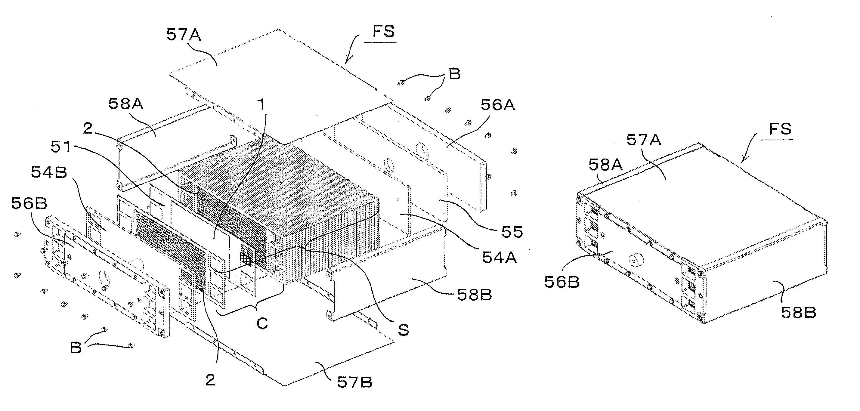
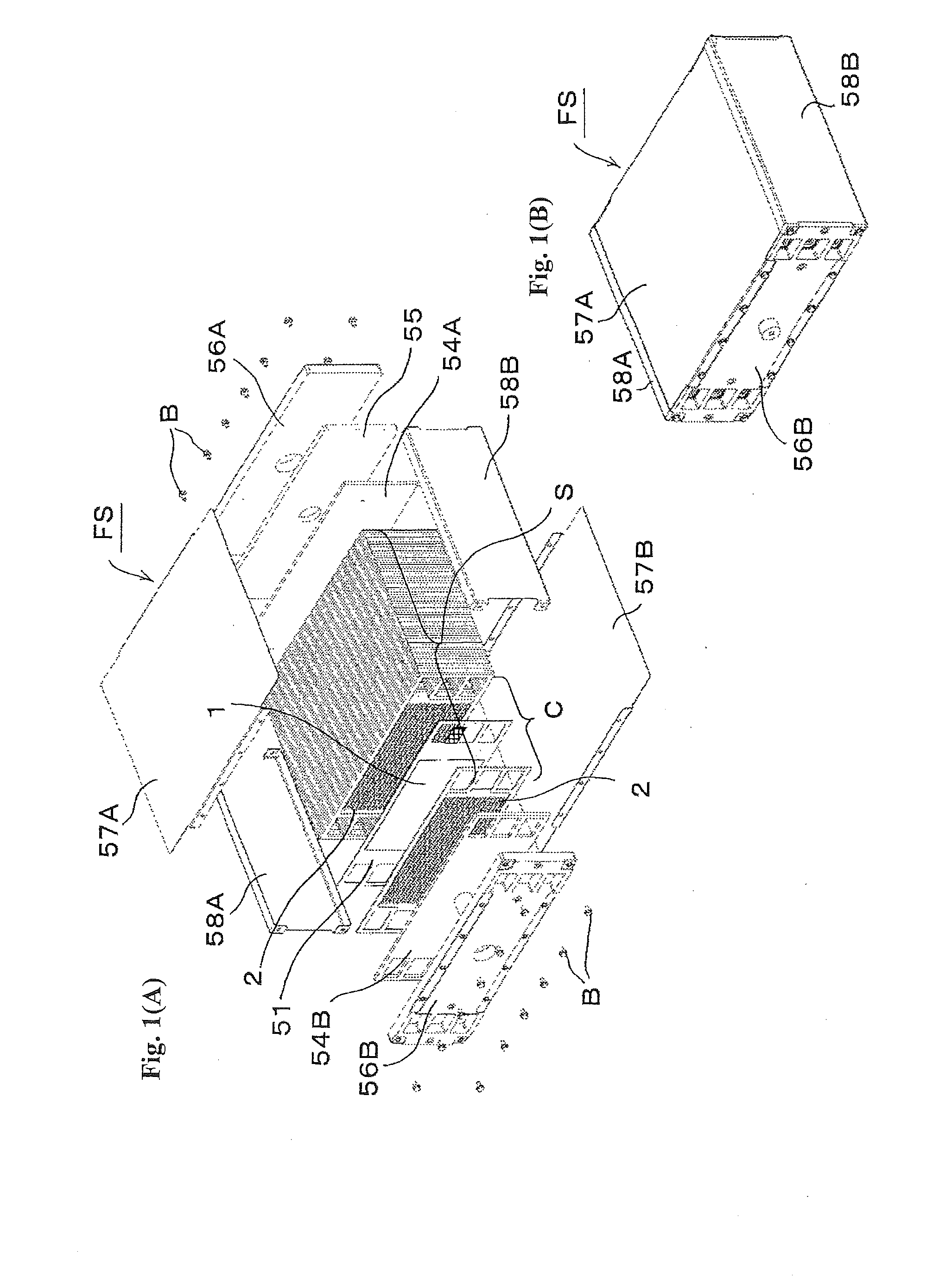
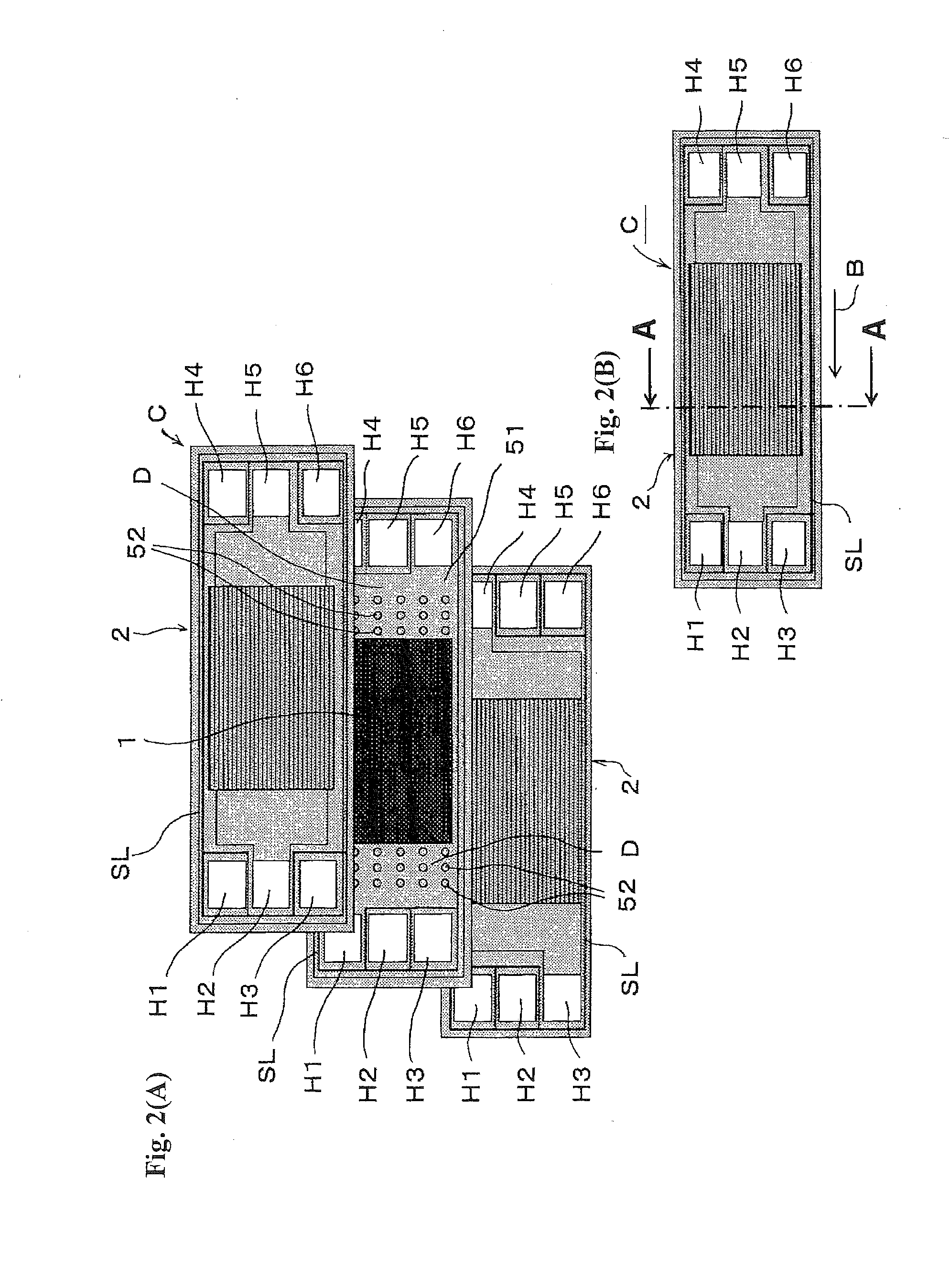
[0021]The fuel cell stack FS of FIG. 1(A) includes a plurality of rectangular plate single cells C that are stacked together to form a stack S, an end plate 56A provided on one end in the stacking direction (...


PUM


Abstract

A fuel cell stack has a stacked plurality of single cells. Each of the single cells has a membrane electrode assembly, and a pair of separators sandwiching the membrane electrode assembly therebetween. A cooling fluid channel where a cooling fluid flows is formed between adjacent single cells. The fuel cell stack further comprises a displacement absorbing member disposed in the cooling fluid channel to absorb a displacement between the single cells. The displacement absorbing member comprises a channel flow resistance reduction structure that reduces a channel flow resistance of the cooling fluid channel against the cooling fluid.

Description

BACKGROUND[0001]1. Technical Field[0002]The present invention relates to a fuel cell such as a polymer electrolyte fuel cell (PEFC), particularly to a fuel cell stack that has a cooling fluid channel formed between stacked single cells.[0003]2. Related Art[0004]One of such fuel cell stacks is described in, for example, Patent Document 1 where it is referred to as a fuel cell. The fuel cell described in Patent Document 1 is composed of a stacked plurality of fuel cells. Each of the fuel cells includes a hydrogen electrode with an uneven cross-section and an oxygen electrode including an drain layer with an uneven cross-section, which are disposed on opposite sides of an MEA (membrane electrode assembly), and further includes flat plate separators disposed on the outer sides of the hydrogen electrode and the oxygen electrodes to form a hydrogen channel and an oxygen channel in the respective interfaces with the electrodes. Furthermore, the fuel cell includes a coolant channel portion ...

Claims


Application Information

Patent Timeline
IPC IPC(8): H01M8/02H01M8/10H01M8/24
CPCH01M8/0267H01M8/2465H01M8/1004H01M2008/1095H01M8/0206H01M8/0258H01M8/0297H01M8/2483F28D2021/0043F28D9/005F28F2240/00F28F2265/26Y02E60/50H01M8/241H01M8/0265
Inventor FUKUYAMA, YOSUKEIRITSUKI, KEITATERADA, YUSUKETAJIMA, NORIHIRO
Owner NISSAN MOTOR CO LTD
Learn More