Circulation type line-up conveying apparatus

a conveying apparatus and line-up technology, applied in the direction of conveyor parts, mechanical conveyors, transportation and packaging, etc., can solve the problems of high cost and other problems, and achieve the effects of avoiding noise and the like, avoiding belt breakage, and reducing maintenance costs

Inactive Publication Date: 2005-12-08
MARUYASU KIKAI KK
View PDF7 Cites 14 Cited by
  • Summary
  • Abstract
  • Description
  • Claims
  • Application Information

AI Technical Summary

Benefits of technology

[0018] In the case of a conveyor, the side plate of which is to forcibly drive, however, since the objects to be conveyed are forcibly conveyed in the direction of rotation of the conveying roller by the driving of the conveyor, the problem is eliminated. In this respect, the driving source of the side conveyor may be either a system for obtaining the force of rotation by taking advantage of the non-contact type power transmission system of the conveying conveyor constituting the present conveying apparatus, or a system for exclusively arranging a driving source.
[0019] The circulation type line-up conveying apparatus according to the present invention is, with the structure described in claim 1, capable of automatically lining up the objects to be conveyed, which are supplied in disorder and in many lines, in a single line lengthwise for forwarding. The objects to be conveyed, overflowed from the line-up line can be automatically returned upstream of the main conveying conveyor for lining up and conveying by means of both the return conveying conveyor and the delivery conveying conveyor, and supplied to the line-up conveying again. Thus, the so-called bridge, in which some objects to be conveyed and other objects to be conveyed on the downstream side (in the vicinity of an outlet) of the main conveying conveyor are intertwined, can be prevented. Moreover, since the driving system of the conveying roller is of the non-contact type driving system using a magnet, it is possible to elimi

Problems solved by technology

In the case of the line-up conveying apparatus described in the Patent Reference 1, however, since the plurality of belt conveyors are contiguously provided in a single line lengthwise and arranged, large installation space for the line-up conveying apparatus is required, and further as pretreatment for supplying the products to the line-up conveying apparatus, conveyors and the like for lining up in a single line sideways, having a forcible feeding finger for conveying the object group in a predetermined

Method used


Image

  • Circulation type line-up conveying apparatus
  • Circulation type line-up conveying apparatus
  • Circulation type line-up conveying apparatus

Examples


Embodiment Construction

[0033] Hereinafter, with reference to the drawings, the description will be made of an embodiment of the present invention.

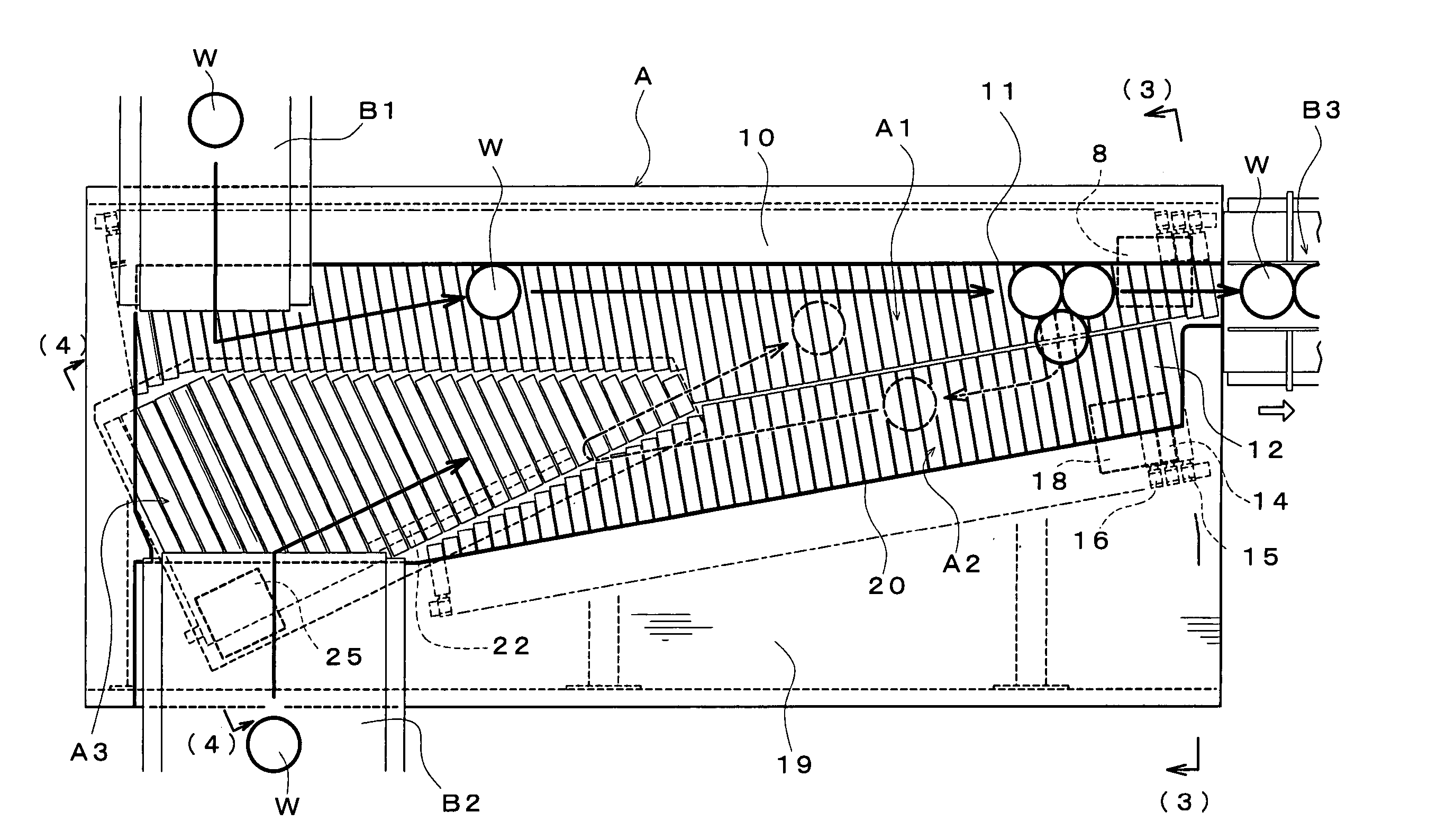
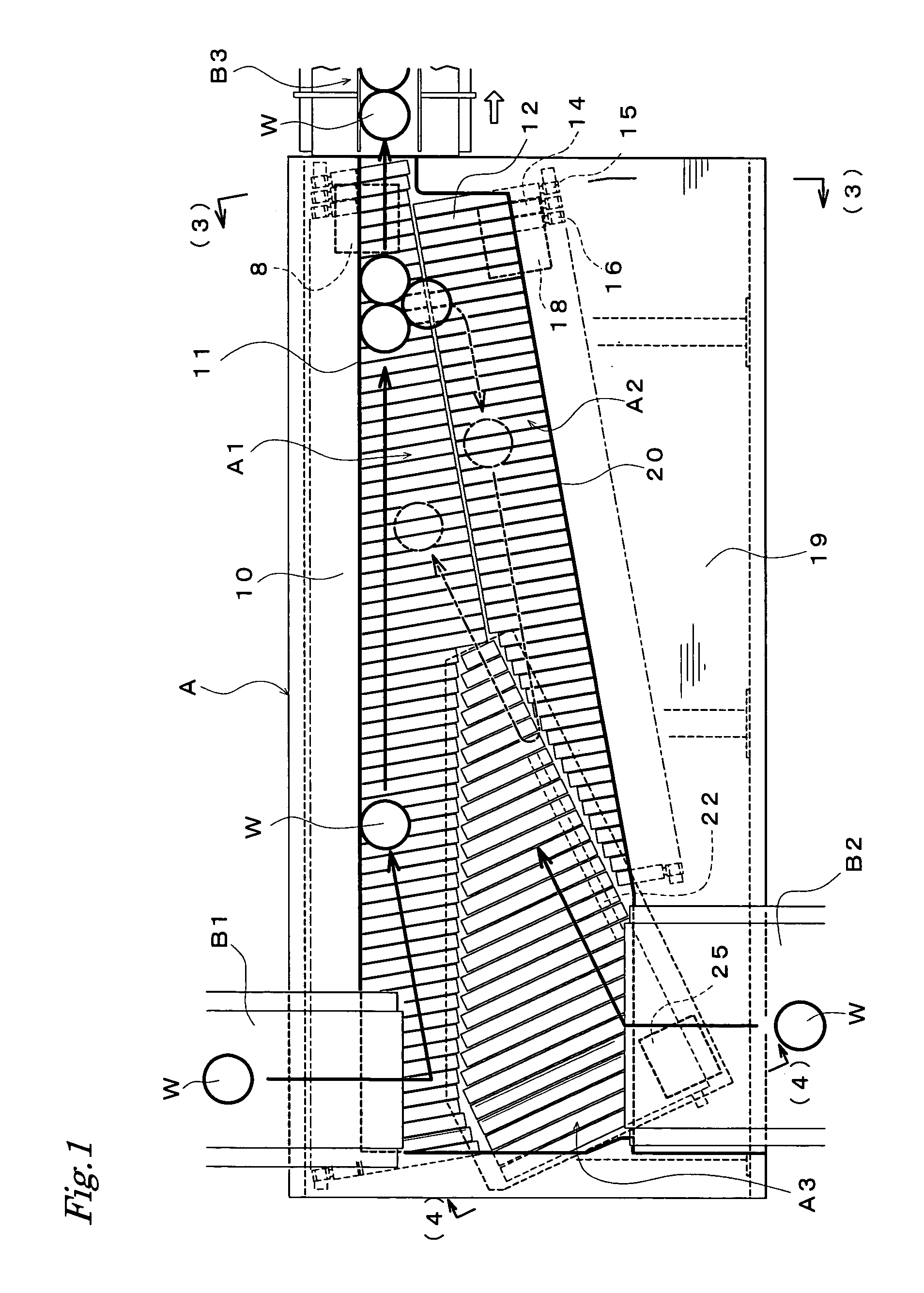
[0034]FIG. 1 is a plan view showing an outline of a circulation type line-up conveying apparatus A according to the present invention, which is formed of three conveying roller conveyors: a main conveying conveyor A1, a return conveying conveyor A2 and a delivery conveying conveyor A3. On the upstream side of the main conveying conveyor A1 and the delivery conveying conveyor A3 in the respective conveying directions, supply conveyors B1 and B2 supplying the objects W to be conveyed are arranged while on the downstream side of the main conveying conveyor A1, a carrying-out conveyor B3 conveying the objects W to be conveyed lined up in a single line lengthwise to the next process has been arranged.

[0035] The above-described main conveying conveyor A1 is constituted by a cantilever type roller conveyor in which a conveying roller drivingly rotating in accordance ...


PUM


Abstract

This apparatus automatically lines up and forwards in a single line lengthwise objects supplied at random and in many lines and yet automatically returns objects overflowed from a line-up line to upstream.
This apparatus includes: a cantilever type main conveying conveyor (A1) constructed from a conveying roller of a obliquely arrangement drivingly rotated by transmission system of non-contact, a return conveying conveyor (A2) formed of drivingly rotating in a direction opposite to the conveying direction of the main conveying conveyor, and a delivery conveying conveyor (A3) for transferring objects conveyed by the return conveying conveyor to upstream. The return conveying conveyor (A2) has been arranged with an open end side of the conveying roller placed close to a side portion on the open end side of the conveying roller on the downstream side along the conveying direction in the main conveying conveyor (A1).

Description

BACKGROUND OF THE INVENTION [0001] 1. Field of the Invention [0002] The present invention relates to a conveying apparatus for lining up objects (products) to be conveyed, which are carried out of a manufacturing line, in a single line lengthwise for conveying, and more particularly to a circulation type line-up conveying apparatus for lining up objects to be conveyed, which are irregularly carried out, in a single line lengthwise for the next process for conveying, and automatically returning objects to be conveyed which have been overflowed from a line-up line, upstream for conveying. [0003] 2. Description of the Related Art [0004] In order to individually package products, which are irregularly carried out of the manufacturing line, in the next process, it is necessary to line up and convey the products. For example, in a bun factory, in order to individually package buns to be carried out of the manufacturing line, it is necessary to line up those buns in a single line lengthwis...

Claims


Application Information

Patent Timeline
IPC IPC(8): B65G47/30B65G47/12B65G47/68
CPCB65G2201/0202B65G47/682
Inventor YODA, KAZUE
Owner MARUYASU KIKAI KK
Why Eureka
Try Eureka