Vehicle mounted night vision imaging system and method

a technology of night vision imaging and vehicle mounted, applied in the direction of polarising elements, using reradiation, instruments, etc., can solve the problems of limiting the visibility range of the driver, glare (“blinding”) other drivers, and the use of high beam lights or alternative high-powered lights is not customary nor allowed

Active Publication Date: 2005-12-08
ELBIT SYST LTD
View PDF11 Cites 153 Cited by
  • Summary
  • Abstract
  • Description
  • Claims
  • Application Information

AI Technical Summary

Benefits of technology

[0025] According to another embodiment of the present invention, providing the intensifying ability as a function of a relevant target range from the system

Problems solved by technology

When driving a vehicle at night, or in poor visibility conditions, the insufficient illumination generated by a vehicle's headlights and/or any ambient road lighting, nearly always limits the driver's visibility range.
However, the light system of vehicles, even when the headlamps are set to the high beam lights state, will generally illuminate a distance not exceeding approximately 200 meters, i.e. approximately 6 seconds of driving at a speed of 120 km/h.
However, It should be noted that the use of high beam lights or alternative high powered lights is not neither customary nor allowed for continuous driving, as it causes glare (“blinding”) other drivers.
This seems to mean that drivers are driving currently under conditions of insufficient visibility range or, at least, in a state on the borderline of the required range of safe vision, and are, therefore, endangering themselves and others.
Simply improving vehicle headlights to increase their illumination range may not be a suitable solution, because blinding of other drivers should be avoided, and also due to technological limitations.
The system described in the '439 patent is based on a thermal camera, which does not offer a solution for perceiving differences in colors and shades of gray (a thermal camera displays heat distinctions and emissivity only).
The system is heat sensitive and therefore, does not detect elements' temperature if equal to the roa

Method used


Image

  • Vehicle mounted night vision imaging system and method
  • Vehicle mounted night vision imaging system and method
  • Vehicle mounted night vision imaging system and method

Examples


Embodiment Construction

[0040] The following description is presented to enable one ordinary skilled in the art to make and use the invention as provided in the context of a particular application and its requirements. Various modifications to the described embodiments will be apparent to those with skill in the art, and the general principles defined herein may be applied to other embodiments. Therefore, the present invention is not intended to be limited to the particular embodiments shown and described, but is to be accorded the widest scope consistent with the principles and novel features herein disclosed. In other instances, well-known methods, procedures, and components have not been described in detail so as not to obscure the present invention.

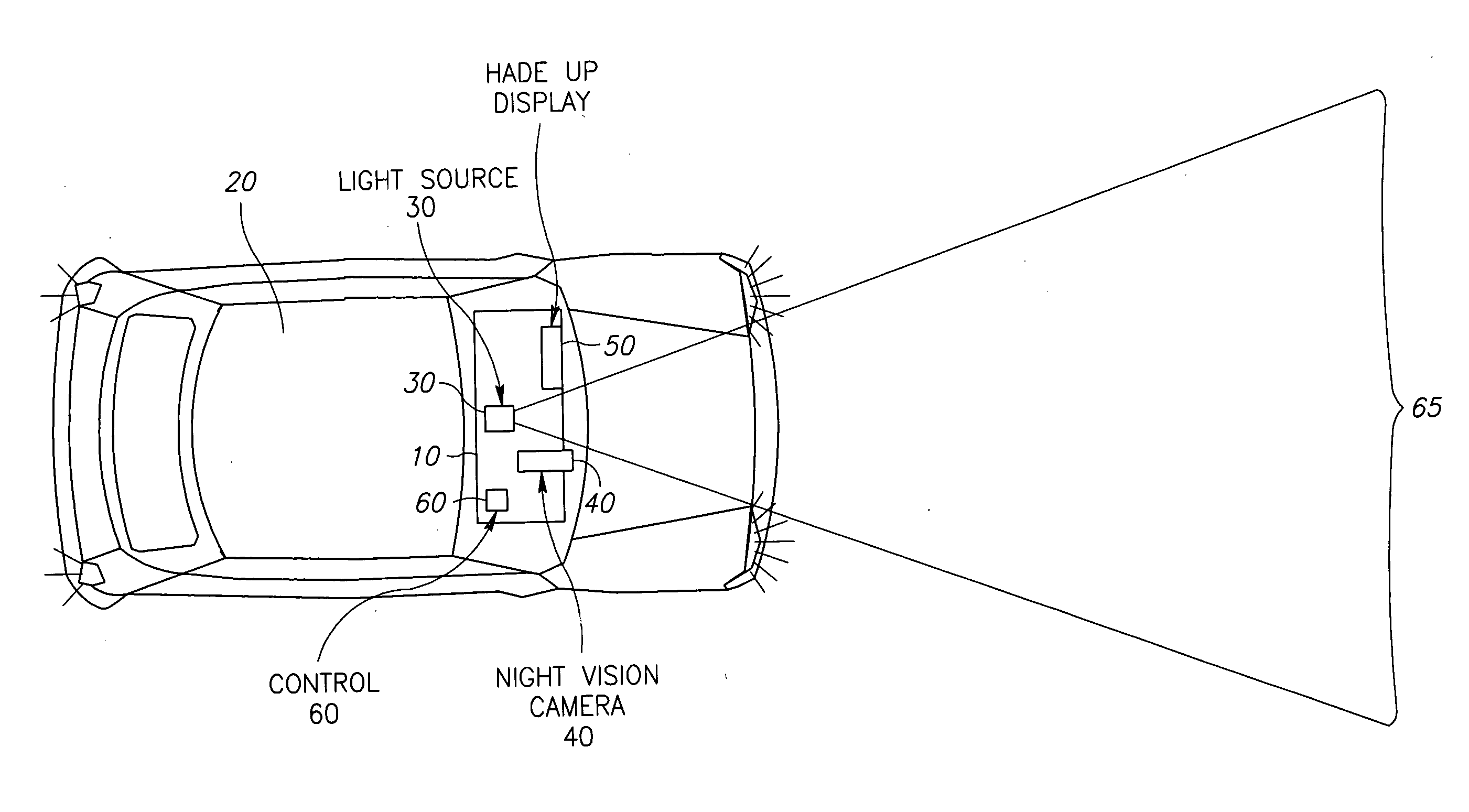
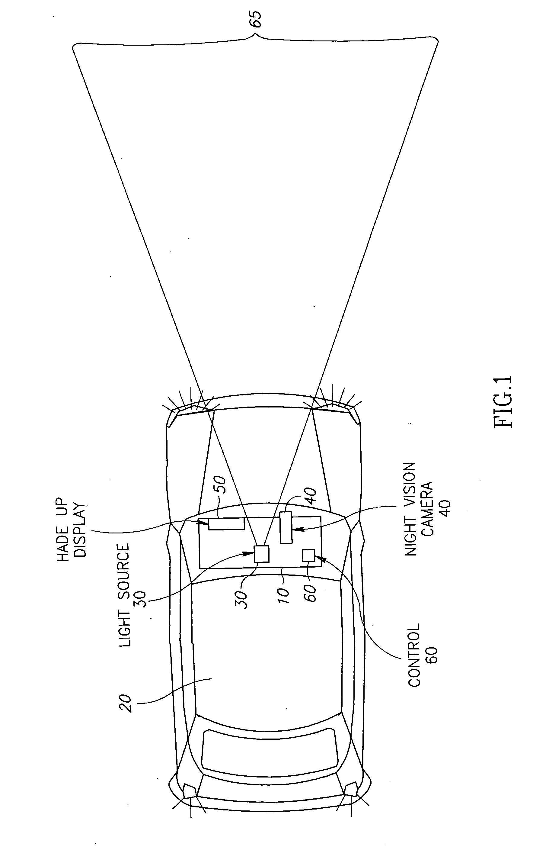
[0041] Referring to Drawing No. 1, the drawing constitutes an illustration of a general configuration of the night imaging system 10 according to an embodiment of the present invention, installed in a vehicle 20. The vehicle may be a road-traveling vehicle,...


PUM


Abstract

A vehicle mounted imaging system and method, enabling selective imaging of objects in a low-visibility environment. The system includes a light source providing non-visible light pulses and a camera having an image intensifier enabled to gate selected received images. The light source may be a laser generator, which may be enabled to generate a pulse width related to the depth of a field to be imaged. The gated image intensifier may determine gating time spans according to the depth of a field to be imaged.

Description

FIELD OF THE INVENTION [0001] The present invention relates to the field of night imaging and display systems in general, and, more particularly, to imaging and display systems applicable for vehicular use and to operation methods implemented in such systems. BACKGROUND OF THE INVENTION [0002] When driving a vehicle at night, or in poor visibility conditions, the insufficient illumination generated by a vehicle's headlights and / or any ambient road lighting, nearly always limits the driver's visibility range. When driving, the driver needs a sufficient range, hence time, to identify a danger from a distance and to react accordingly. The range of vision an alert driver requires to escape danger may be calculated empirically. It is customary to calculate the range required by multiplying the driving speed by the time needed for the combined human and vehicle reaction time. This time may range from 6 to 10 seconds for highway driving to more than double for heavy off-highway vehicle, an...

Claims


Application Information

Patent Timeline
IPC IPC(8): B60R11/02B60R1/00G01S7/484G01S7/489G01S7/495G01S7/51G01S17/18G01S17/89G02B5/30G02B23/12G02B27/00G02B27/01H01L27/00H04N7/18
CPCG01S7/484G02B2027/014G01S7/495G01S7/51G01S17/107G01S17/89G02B5/30G02B23/12G02B27/01G02B27/0101G02B2027/0118G02B2027/012G02B2027/0127G02B2027/0138G01S7/489G01S17/18
Inventor DAVID, OFERBORENSTEIN, YEHUDA
Owner ELBIT SYST LTD
Why Eureka
Try Eureka