

Cover of air bag apparatus and manufacturing method thereof
- Summary
- Abstract
- Description
- Claims
- Application Information
AI Technical Summary
Benefits of technology
Problems solved by technology
Method used
Image

Examples
first embodiment
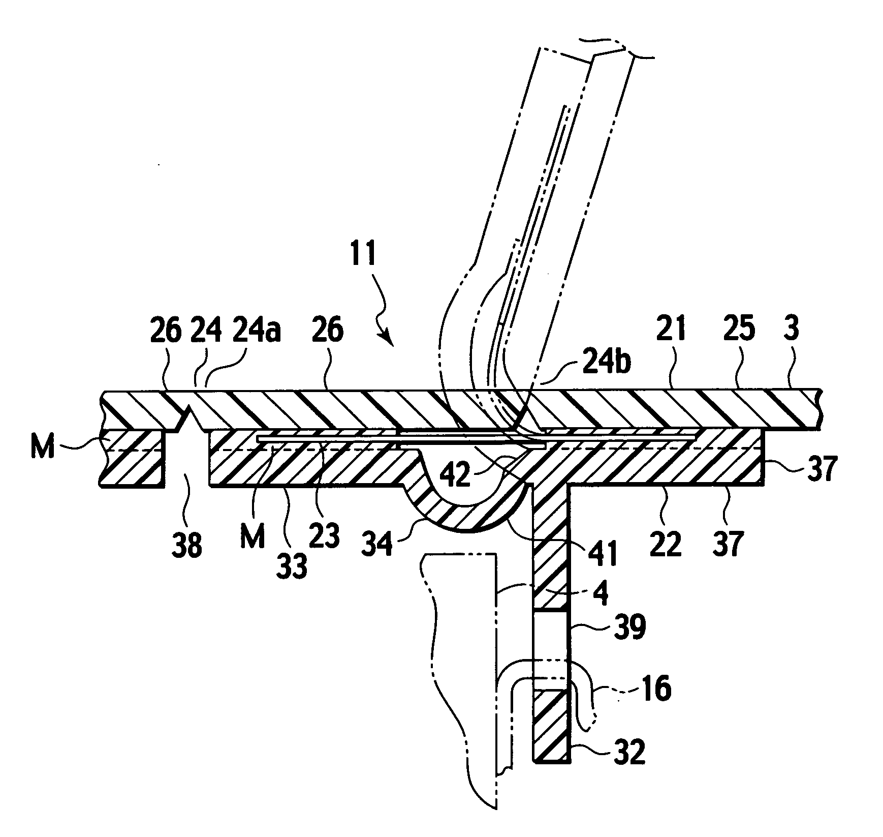
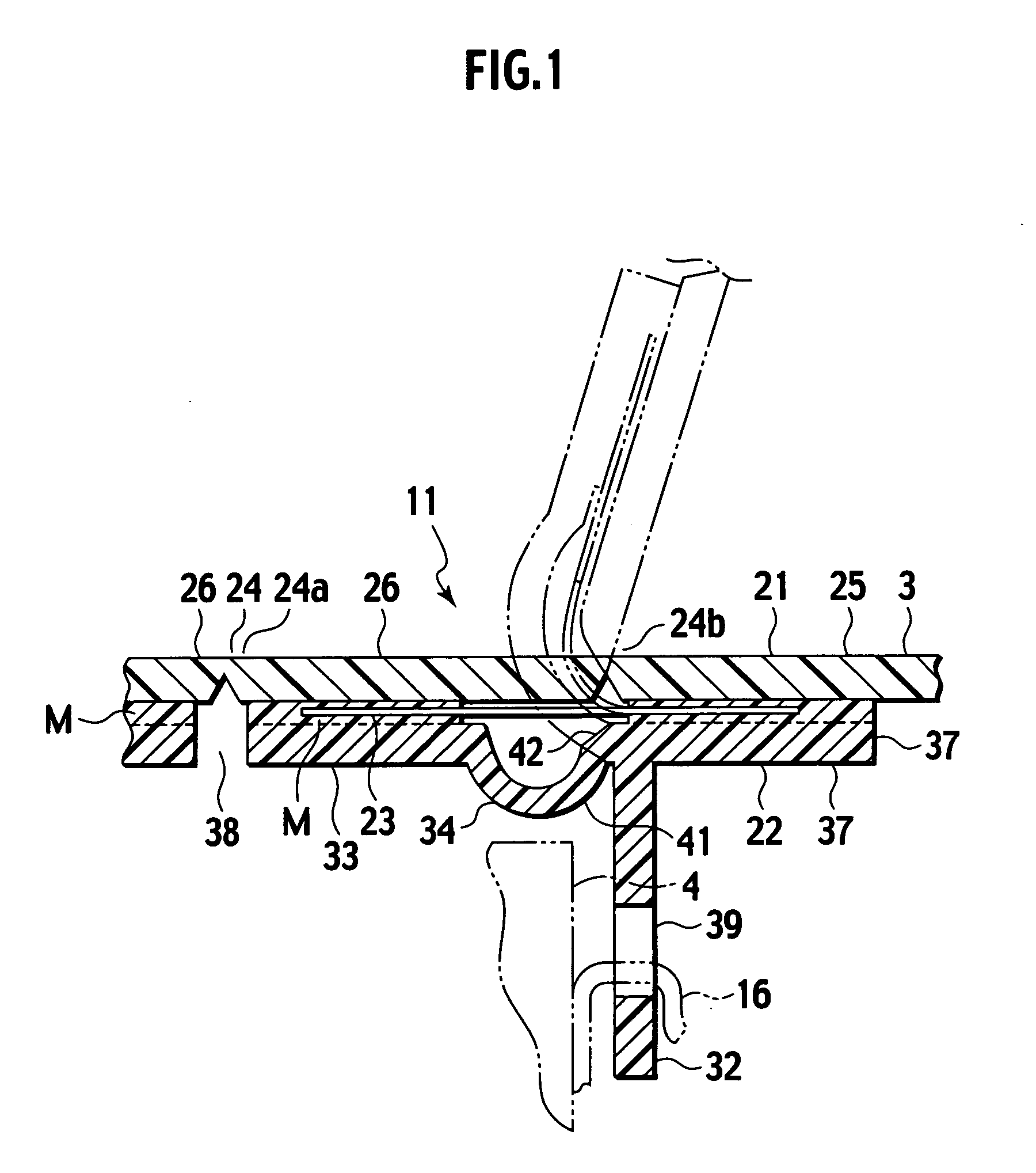
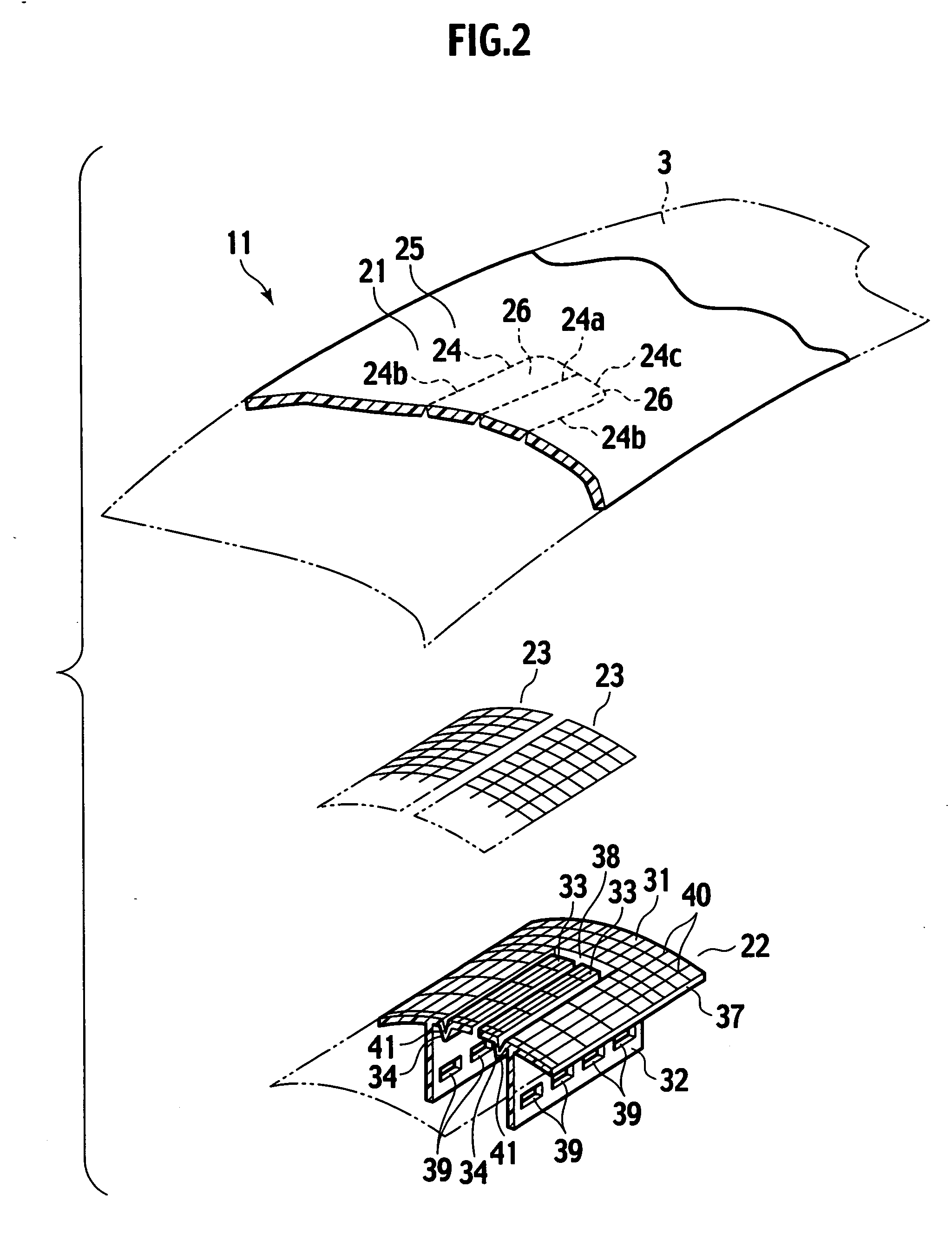
[0069] Referring to FIG. 1, for the present invention, reference numeral 1 denotes an air bag apparatus, which constitutes an air bag apparatus 1 for a front sheet passenger equipped in an instrument panel portion 3 of vehicle. The instrument panel 3 is provided over substantially entire length in the vehicle width direction of the front portion of a vehicle compartment and a front window glass is located above this instrument panel portion 3. The air bag apparatus 1 is accommodated inside this instrument panel portion 3 such that it opposes a front seat passenger. This air bag apparatus comprises a case body 4 called retainer or reaction can, an inflator (not shown) attached to the bottom portion of this case body 4, an air bag (not shown) accommodated in a folded condition above the inflator and a cover (cover body) 11 for covering an opening portion in the upper portion of the case body 4. This air bag apparatus 1 is mounted on a vehicle body by fixing the case body 4 to a reinfo...
second embodiment
[0101] the present invention will be described with reference to the accompanying drawings hereinafter.
[0102]FIG. 12 is a perspective view of an air bag apparatus having a cover (cover body) 100 for covering an air bag module installed inside an instrument panel 102 of a vehicle. FIG. 13 is a back side view of the panel main body, FIG. 14 is a sectional view taken along the line XIV-XIV of FIG. 12 and FIG. 15 is an enlarged view of an encircled section XV in FIG. 13.
[0103] The instrument panel 102 shown in FIGS. 12, 13 is provided with an opening portion 102a which is a projection port of an air bag 108 at an opposing face 102b opposing a vehicle compartment. And the opening portion 102a of the instrument panel 102 is covered with the cover 100 which includes an outer panel (panel main body) 101 constituting automobile interior material and an inner panel (backing member) 105. The outer panel 101 is constructed to cover an opening portion 102a provided on the opposing face 102b opp...
PUM
| Property | Measurement | Unit |
|---|---|---|
| Elongation | aaaaa | aaaaa |
| Pressure | aaaaa | aaaaa |
| Distance | aaaaa | aaaaa |
Abstract
Description
Claims
Application Information