Insulating structure having combined insulating and heat spreading capabilities

Inactive Publication Date: 2005-12-08
WL GORE & ASSOC INC
View PDF20 Cites 68 Cited by
  • Summary
  • Abstract
  • Description
  • Claims
  • Application Information

AI Technical Summary

Benefits of technology

[0006] In yet another aspect, the invention provides a method of reducing heat at hot-spots of a portable electronic device comprising the steps of providing a portable electronic device having at least one heat generating component and an enclosure having a surface, and placing

Problems solved by technology

In portable electronic devices such as notebook computers, PDA's (personal digital assistants), cell phones and the like, as the size of the physical envelope or enclosure of the device decreases, and/or functionality of the device increases, thermal management becomes a challenge.
Outer enclosure surfaces that are in direct contact with a user may thus become uncomfortably hot, particularly i

Method used


Image

  • Insulating structure having combined insulating and heat spreading capabilities
  • Insulating structure having combined insulating and heat spreading capabilities
  • Insulating structure having combined insulating and heat spreading capabilities

Examples


Embodiment Construction

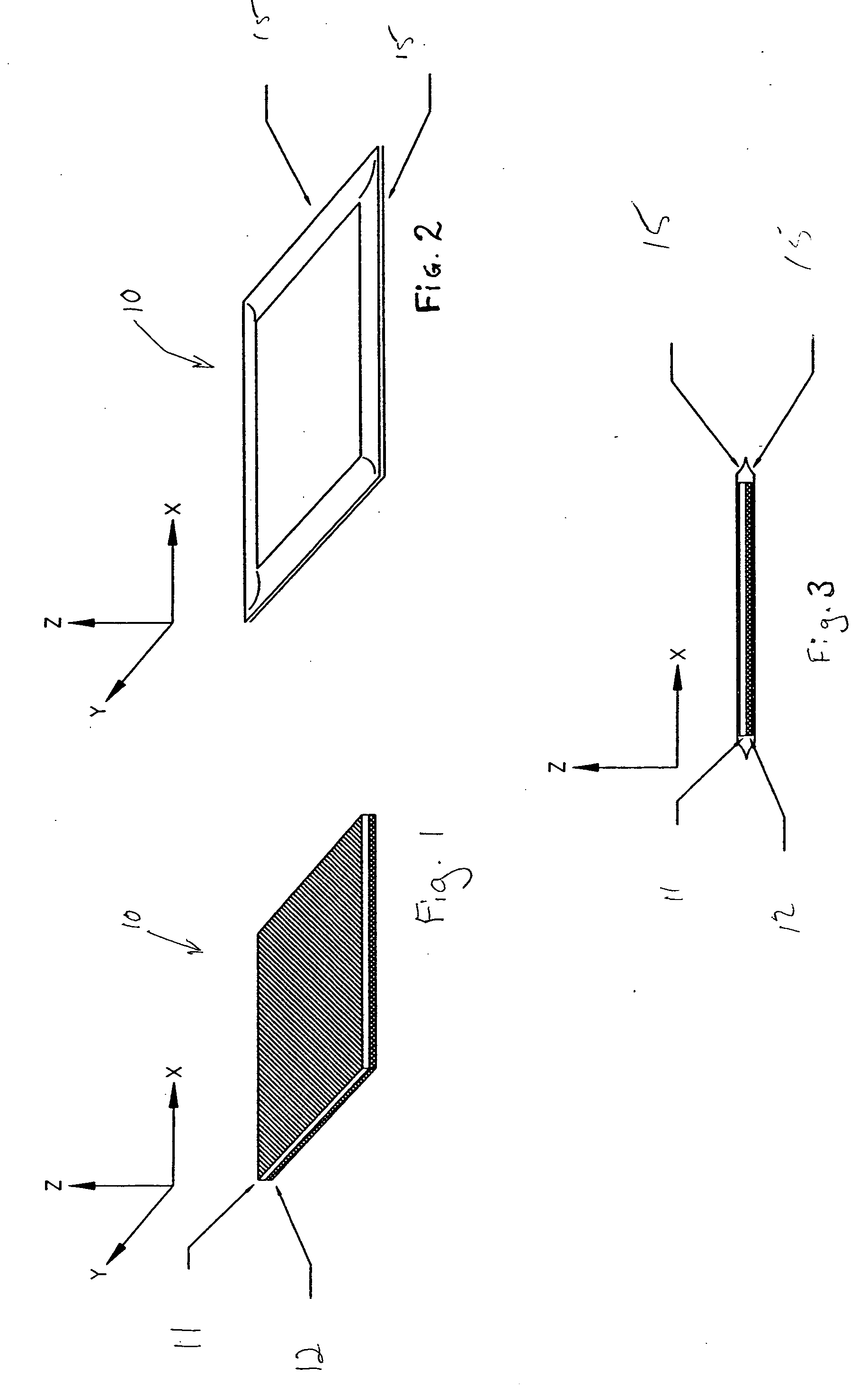
[0012] The invention will now be described in connection with the associated figures. FIG. 1 illustrates an exemplary embodiment of an insulating structure 10. In this embodiment, insulating structure 10 includes an insulating material 11 and a heat spreading material 12.

[0013] Insulating material 11 is any material that inhibits heat from being conducted in the Z-direction (see figures). Preferably, insulating material 11 has a Z-direction thermal conductivity of less than air, or about 25 miliWatts per meter degree Kelvin (mW / m-K) but may be higher, depending upon the application requirements. Also preferably, the insulating material 11 is less than about 2 mm thick and is compressible by at least 10% with a pressure of about 50 psi. Insulating material 11 compositions include versions that are designed to operate in a vacuum (also called vacuum insulation panels), and versions that are designed to operate at atmospheric pressure (also called non-vacuum insulation panels). Approp...


PUM


Abstract

The present invention provides an insulating structure comprising an insulating material and a heat spreading material. The invention further provides a portable electronic device comprising at least one heat generating component, an enclosure, and an insulating structure, wherein the insulating structure comprises an insulating material and a heat spreading material.

Description

BACKGROUND OF THE INVENTION [0001] In portable electronic devices such as notebook computers, PDA's (personal digital assistants), cell phones and the like, as the size of the physical envelope or enclosure of the device decreases, and / or functionality of the device increases, thermal management becomes a challenge. Increased functionality often generates more heat in certain components of electronic devices. Reduced size of the physical envelope of the device positions heat-generating components in closer proximity to outer enclosures, increasing the ease at which the components conduct heat to the surfaces of outer enclosures. Outer enclosure surfaces that are in direct contact with a user may thus become uncomfortably hot, particularly in locations directly adjacent heat generating components. These are often called hot-spots. [0002] One way that is currently used to deal with such hot-spots is to use a heat spreading material, which serves to spread the heat generated by heat-ge...

Claims


Application Information

Patent Timeline
IPC IPC(8): G06F1/20H01L23/367H05K7/20
CPCG06F1/203H01L23/3675H01L2924/0002H01L2924/00
Inventor REIS, BRADLEY
Owner WL GORE & ASSOC INC
Why Eureka
Try Eureka