Planar light source device and display device using the same

Inactive Publication Date: 2005-12-08
MITSUBISHI ELECTRIC CORP
View PDF1 Cites 67 Cited by
  • Summary
  • Abstract
  • Description
  • Claims
  • Application Information

AI Technical Summary

Benefits of technology

[0014] According to the present invention, each of light source units includes the light guiding rod and at least one point light source. The light source units are used in place of the conventional linear light sources (fluorescent tubes), and thus the planar light source device of the present invention contains no mercury acting as environmental load material. Furthermore, no leak current occurs between each light guiding rod and the housing, and thus the distance between each light guiding rod and the housing can be reduced. Still furthermore, the light guiding rods of the light source units can be designed to be smaller in volume and lighter in weight as compared with the light guiding plates used in the conventional edge light type planar light source device. In addition, each light guiding rod is provided

Problems solved by technology

However, when the distance from the light source to the light emission face is small, unevenness in brightness (in general, light is bright just above a linear light source whereas light is dark between linear light sources) is easily visually identified, and thus it is necessary to increase the distance from the light source to the light emission face.
Furthermore, when the distance between each light source and a metal housing disposed at the reflection face side so as to confront the light emission face is small, leak current occurs between the metal housing and each light source, so that the linear light sources are not normally turned on.
According to the illumination device proposed in JP-A-2000-310776, it is possible to reduce the distance from the main light source (fluorescent tube) to the light emission face, however, it is impossible to reduce the distance

Method used


Image

  • Planar light source device and display device using the same
  • Planar light source device and display device using the same
  • Planar light source device and display device using the same

Examples


Example

First Embodiment

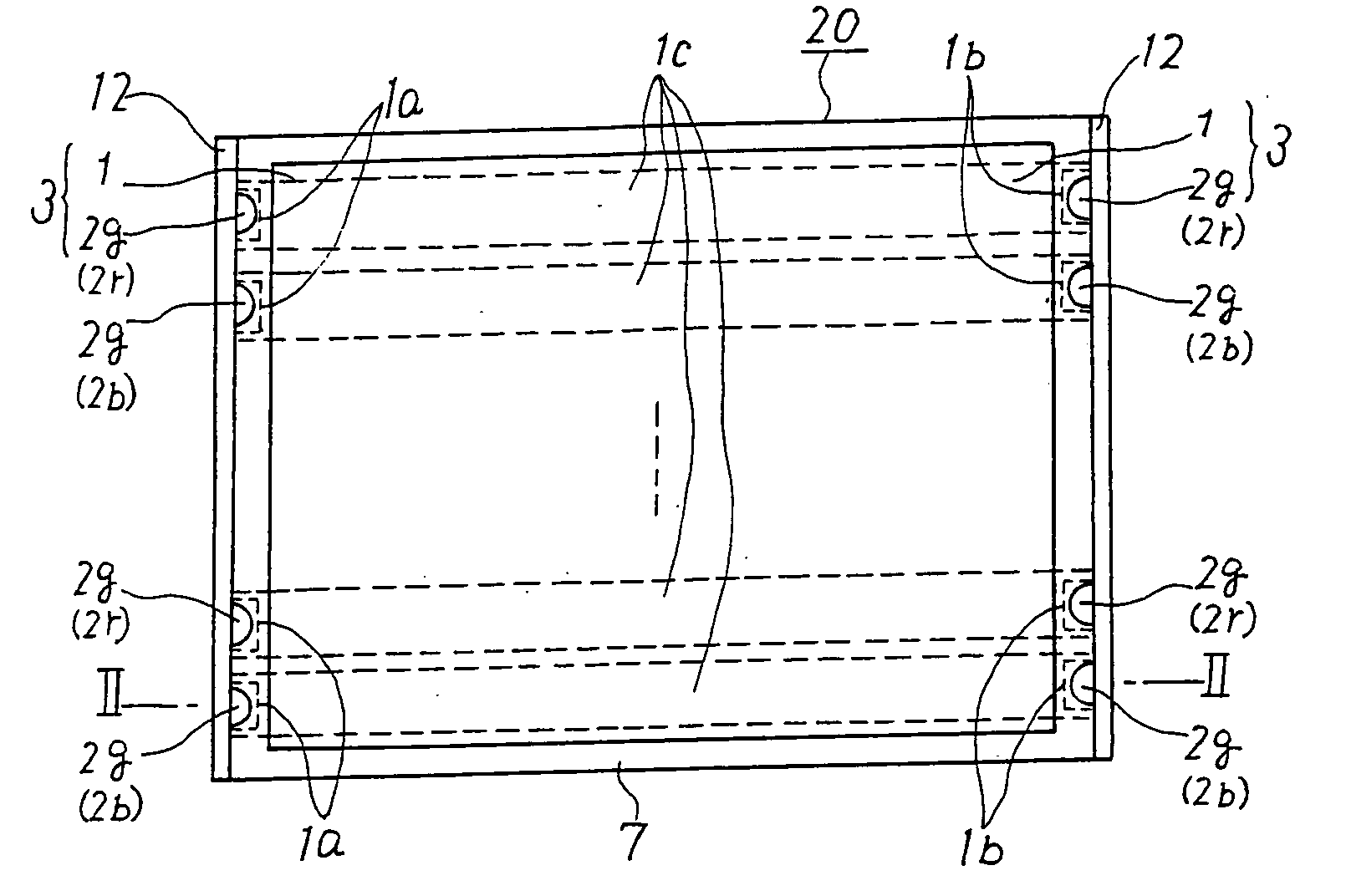
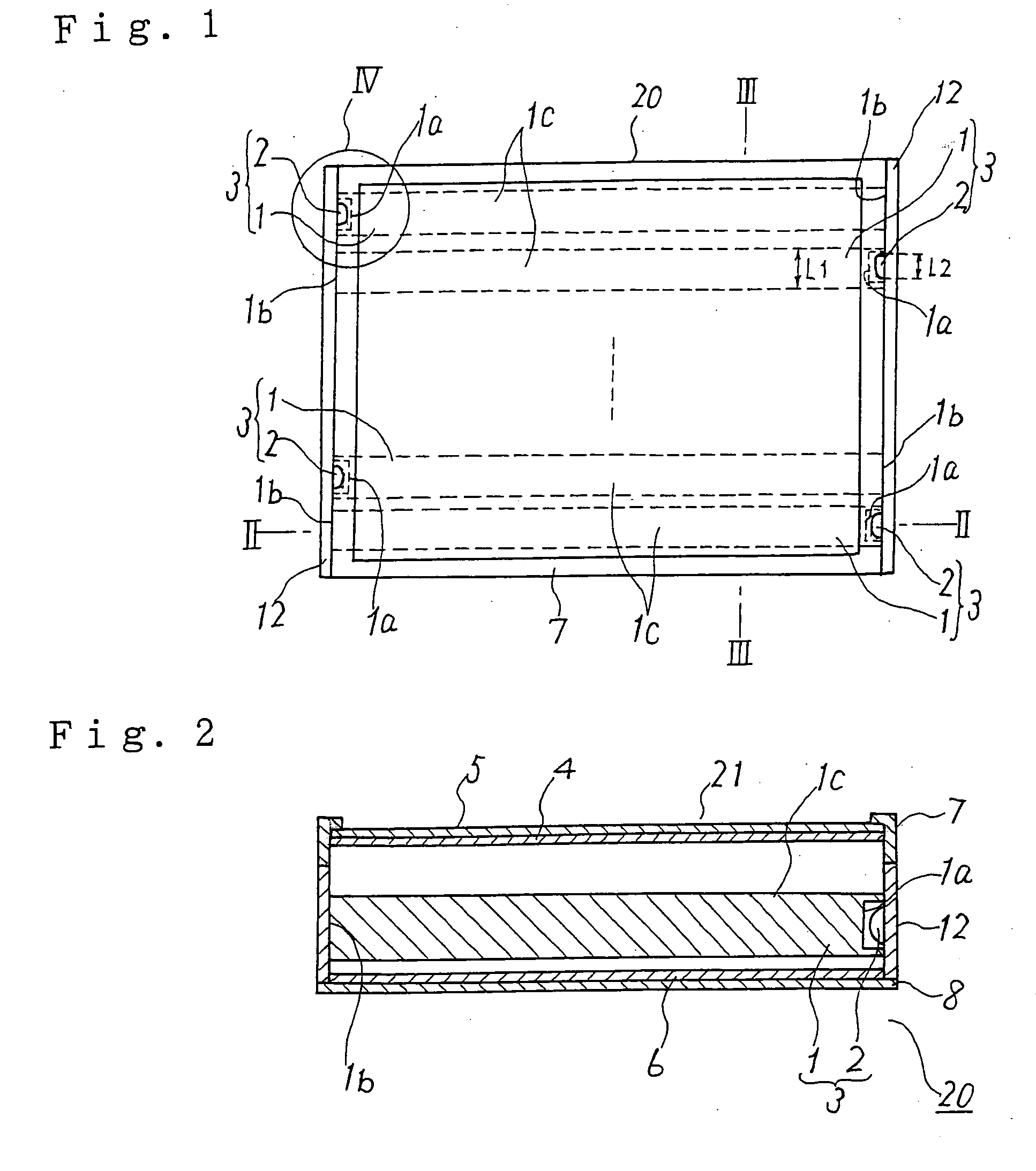
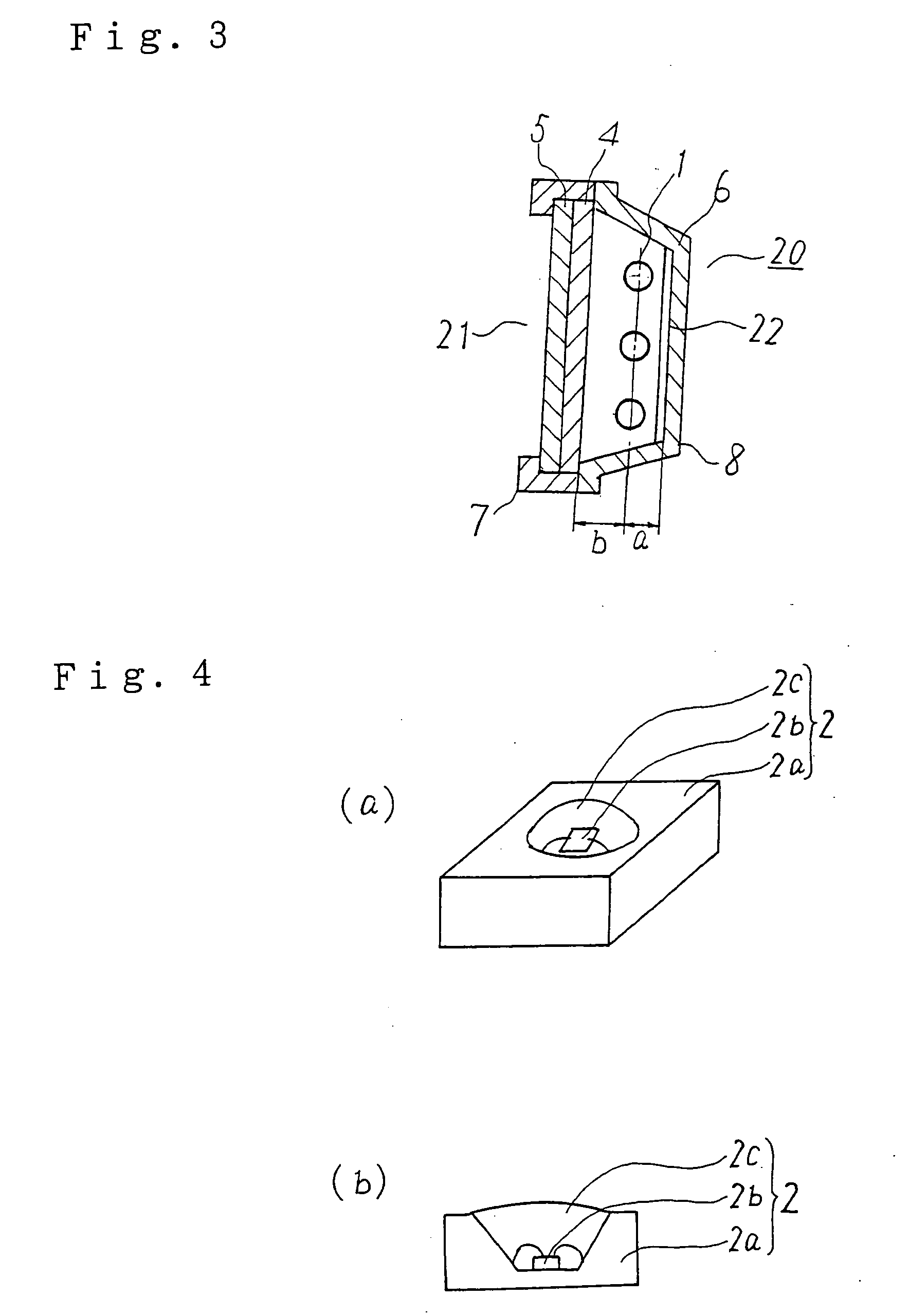
[0032]FIG. 1 is a plan view showing a planar light source device according to a first embodiment, FIG. 2 is a horizontally sectional view showing the cross-section of a part indicated by II-II of FIG. 1, and FIG. 3 is a vertically sectional view showing the cross-section of a part indicated by III-III of FIG. 1. In these figures, the same or corresponding parts are represented by the same reference numerals.

[0033] The planar light source device 20 of the first embodiment includes a metal housing which includes a first frame 7 having an opening portion serving as a light emission face 21 on the upper surface thereof and a second frame 8 surrounding the lower portion of the metal housing, and plural light guiding rods 1 which are formed of acrylic resin, polycarbonate resin or the like, or a transparent material such as glass or the like and arranged in parallel to one another in the metal housing. Relating to each light guiding rod 1, a point light source 2 is dispo...

Example

Second Embodiment

[0049]FIG. 9 is a plan view showing a planar light source device according to a second embodiment of the present invention. As shown in FIG. 9, the planar light source device 20 according to the second embodiment is designed so that plural light source units 3 achieved by arranging point light sources 2 at both the end faces 1a, 1b of respective light guide rods 1 is disposed in the vertical direction (the direction indicated by an arrow in FIG. 9), that is, in parallel to the short side of the substantially rectangular opening portion (light emission face 21) having long sides and short sides. In FIG. 9, the same elements as or corresponding parts to those of the first embodiment are represented by the same reference numerals, and the description thereof is omitted.

[0050] Recently, large-size display devices such as 30-inch wide type, 40-inchi wide type, etc. have been strongly required. In the case of such a large-size liquid crystal display device, when the lin...

Example

Third Embodiment

[0052]FIG. 11(a) is a plan view showing a planar light source device 20 according to a third embodiment of the present invention, and FIG. 11(b) is a horizontally sectional view showing a part indicated by II-II of FIG. 11(a). In FIGS. 11(a) and 11(b), the same elements as or corresponding to the elements of the first and second embodiments are represented by the same reference numerals, and the duplicative description thereof is omitted.

[0053] In the planar light source device 20 of the third embodiment, a red point light source 2r, a green point light source 2g and a blue point light source 2b are used in light source units 3. The numbers of the light source units 3 of the respective colors (red, green and blue) are different among the colors, and in order to achieve a desired color, the numbers of the red and blue light source units are respectively set to 4 while the number of the green light source units is set to 8. Furthermore, as shown in FIG. 11(b), the re...


PUM


Abstract

In a planar light guiding device and a display device, plural light guiding rods are arranged in parallel to one another in a housing having an opening portion serving as a light emission face at the upper surface thereof, and a point light source (LED) 2 is disposed so as to oppose to at least one of both the end faces 1a of each light guiding rod through a space, thereby constituting a light source unit. These light source units are arranged in the metal housing to thereby form the planar light guiding device.

Description

BACKGROUND OF THE INVENTION [0001] 1. Field of the Invention [0002] The present invention relates to a planar light source device and a display device using the planar light source device. [0003] 2. Description of the Related Art [0004] There are known two types of planar light source devices each of which is disposed at the back surface side of a liquid crystal display device. One type of these planar light source devices is called an edge light type, and the other type thereof is called a just-below type. According to the edge light type planar light source device, a light source is disposed at one side surface or at both side surfaces of a light guiding plate of the light source, and lights from the light sources are emitted from the end surfaces of the light guiding plate so that the light is emitted in a planar shape. [0005] The edge light type planar light source device has such a feature that the thickness of the planar light source device can be reduced, however, it needs th...

Claims


Application Information

Patent Timeline
IPC IPC(8): G02F1/1333F21V7/04F21V8/00F21Y101/02G02B6/00G02B6/28G02B6/42G02F1/13357
CPCG02B6/001G02B6/0021G02B6/0068G02B6/0073G02B6/2808G02B6/423
Inventor ICHIKAWA, KOJISAKAI, SEIJIYONEDA, TOSHIYUKI
Owner MITSUBISHI ELECTRIC CORP
Why Eureka
Try Eureka