Packet generation method, communication method, packet processing method and data structure

a packet generation and communication method technology, applied in data switching networks, multiplex communication, digital transmission, etc., can solve the problem of requiring a large amount of labor, and achieve the effect of greater

Active Publication Date: 2005-12-08
SOCIONEXT INC
View PDF20 Cites 49 Cited by
  • Summary
  • Abstract
  • Description
  • Claims
  • Application Information

AI Technical Summary

Benefits of technology

[0007] According to the present invention, provided is a generation method for forming an IP packet using an IP header, wherein included is an option area to which an arbitrary data area is added following an end position indicator representing the end of the option area, and an IP data portion. Further, according to a communication method of this invention, an IP packet, generated using the packet generation method of this invention, is transmitted Furthermore, according to the invention, provided is a data structure for an IP packet formed using an IP header having an option area, which includes an arbitrary data area that follows an option end position indicator, and an IP data portion. According to this arrangement, by employing an IP packet that is generated by adding an arbitrary data area, following an indicator for the end position of the IP header option, a group number, for defining a plurality of communication partners to be combined, can be provided in the data area, and the network grouping can be performed without a VLAN switch being required.
[0008] According to the invention, by employing an IP packet that is generated by adding an arbitrary data area following an indicator for the end position of the IP header option, a group number for defining a plurality of communication partners to be combined can be provided in the data area, and the network grouping can be performed without a VLAN switch being required.
[0009] Further, to change the group number of a group to which a communication apparatus belongs, only the setup of the group number must be changed, and unlike in a case wherein the VLAN switch is employed, a change in the setup related to the overall network and a change in the wiring arrangement are not required. In addition, since the group numbers are managed by the individual communication apparatuses, the simultaneous transmission of an IP packet can be performed for all the communication apparatuses that belong the same group. Moreover, a control command can be additionally included in the IP packet, so that remote control can be employed to control a designated communication apparatus. Further, when the simultaneous transmission function and the remote control function are employed together, a control command can be simultaneously issued to all communication apparatuses belonging to the same group, and for the network, can be increased, e.g., when communication apparatuses are separated to provide a home appliance group and an AV apparatus group for a home network, only the apparatuses in the AV apparatus group can be reset. Furthermore, when group information for a communication packet is held, communication apparatuses belonging to the same group on the network can be identified, and when a communication apparatus that is activated transmits to the network the group to which it belongs, the group information can be updated immediately. For a home network, generally, in the DHCP environment, an IP address is automatically allocated. While a VLAN switch can not cope with an environment wherein a change in an IP address is required each time an allocation occurs, the method of the invention can enable network grouping in the DHCP environment. Therefore, for network grouping in a conventional home network environment, not only are the effects obtained greater than when the VLAN switch is employed, but in addition, a network control function can be provided.

Problems solved by technology

Furthermore, when a group to which a communication apparatus belongs is to be changed, consideration must also be given to changing the setup of the VLAN switch 103 relative to the overall network, as well as changing the wiring, and for the maintenance work that this involves, a great deal of labor is required.

Method used


Image

  • Packet generation method, communication method, packet processing method and data structure
  • Packet generation method, communication method, packet processing method and data structure
  • Packet generation method, communication method, packet processing method and data structure

Examples


first embodiment

[0027]FIG. 4 is a flowchart showing the transmission processing performed by each communication apparatus in accordance with the present invention. The transmission processing will now be described while referring to FIG. 4. First, a communication apparatus generates data to be transmitted to a network (step 401). Then, the communication apparatus obtains its own group number in accordance with the setup value for the communication apparatus that has been stored in advance in an external memory or in an internal memory (step 402).

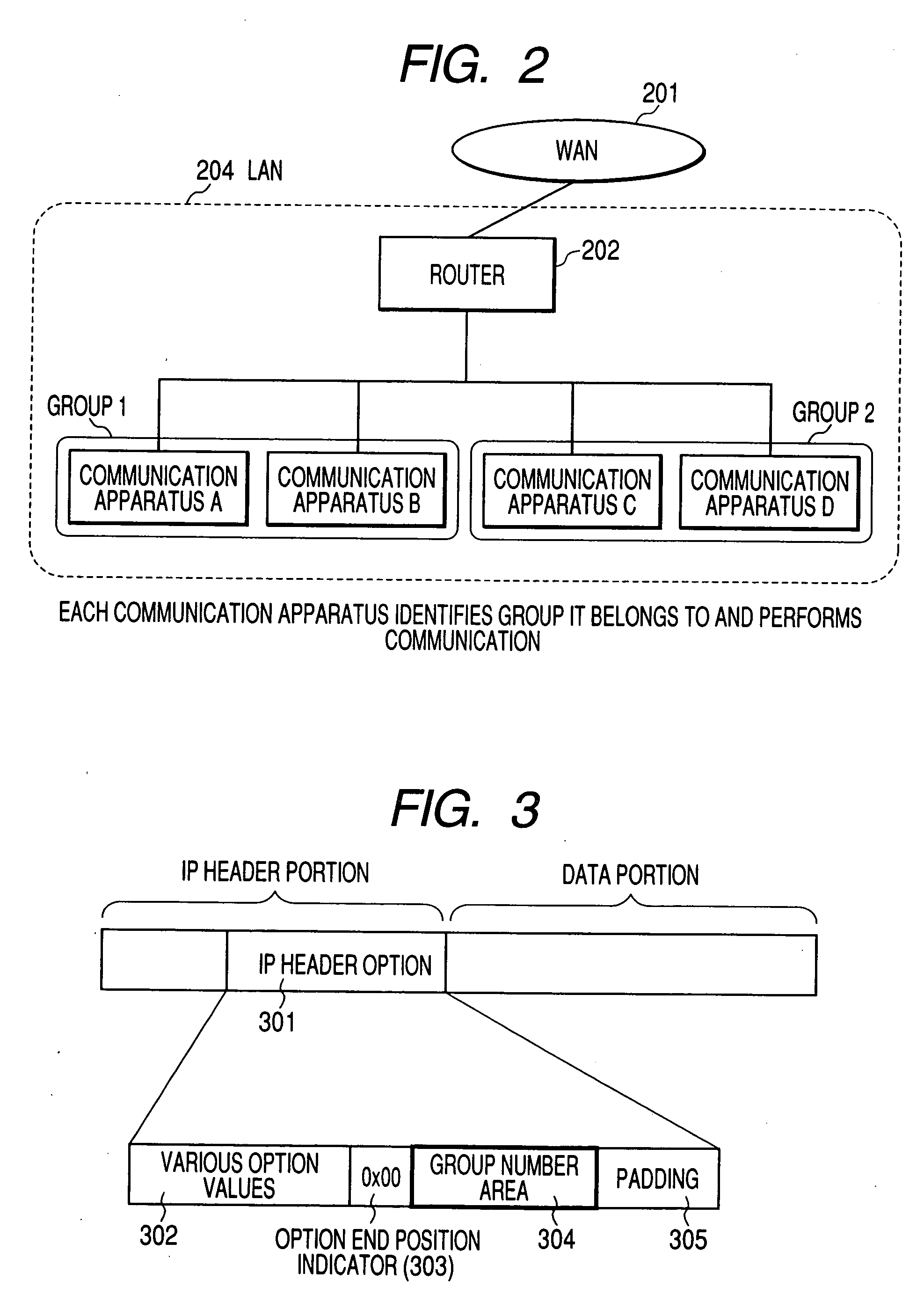
[0028] The communication apparatus designates the group number to be stored following the option end position indicator value “0×00” in the IP header option (step 403). Thereafter, the communication apparatus performs the TCP / IP transmission process to generate, as a network packet, an IP packet (step 404), and transmits the IP packet to the network (step 405). The processing is thereafter terminated.

[0029]FIG. 5 is a flowchart showing the reception proces...

second embodiment

[0033]FIG. 6 is a flowchart showing the reception processing performed by each communication apparatus in the The reception processing will now be described while referring to FIG. 6. First, a communication apparatus receives an IP packet from a network (step 601). Then, the communication apparatus examines the IP header option for the received IP packet, and obtains a group number that is stored following the option end position indicator value “0×00” (step 602).

[0034] The communication apparatus obtains its own group number in accordance with the setup value of the communication apparatus that is stored in an external memory or in the internal memory (step 603). Following this, the communication apparatus compares the two group numbers, and when the two group numbers match, performs a minimum check process that is a simplified normal TCP / IP reception process (step 605), and obtains the received data (step 606). The reception processing is thereafter terminated. An example minimum...

third embodiment

[0037]FIG. 8 is a flowchart showing the transmission processing performed by each communication apparatus in accordance with the First, a communication apparatus generates data to be transmitted to a network (step 801). Then, the communication apparatus obtains its own group number in accordance with the setup value for the communication apparatus that has been stored in advance in an external memory or in the internal memory (step 802).

[0038] Sequentially, the communication apparatus generates a control command to permit the designation of a communication destination to perform a desired process (step 803). Following this, the communication apparatus designates the group number that is to be stored, in the IP header option, following the option end position indicator value “0×00”, and designates the control command generated at step 803 that is to be stored following the group number (step 804). Then, the communication apparatus performs the TCP / IP transmission process to generate...


PUM


Abstract

The objective of the present invention is to perform network grouping without employing a VLAN switch. Communication is performed by using the data structure for an IP packet that includes an IP data portion and an IP header that has an option area, for which a group number area for defining a group, consisting of a plurality of communication apparatuses, is provided as an arbitrary data area following an option end position indicator area.

Description

BACKGROUND OF THE INVENTION [0001] 1. Field of the Invention [0002] The present invention relates to a packet generation method whereby grouping for a network can be performed, and a communication method, a packet processing method and a data structure therefor. [0003] 2. Description of the Related Art [0004] Conventionally, a method for introducing a VLAN switch is employed for IP network grouping. In FIG. 1 is shown a network constructed using a VLAN switch 103. A communication apparatus A and a communication apparatus B belong to the same group 1, and a communication apparatus C and a communication apparatus D belong to the same group 2. In this case, the VLAN switch 103 analyzes an IP packet that is transmitted via the network and distributes the IP packet in accordance with a rule designated in advance for the VLAN switch 103. As a result, of the various communication apparatuses connected to a LAN 104, for example, communication apparatuses for which communication with each ot...

Claims


Application Information

Patent Timeline
Patent Type & Authority Applications(United States)
IPC IPC(8): H04L12/56H04L12/46H04L12/28H04L29/06H04L47/43
CPCH04L69/16H04L69/22H04L69/161
Inventor KANEKO, YOHEI
Owner SOCIONEXT INC
Why Eureka
Try Eureka