Robot, carriage device, and control method using inertia sensor
a technology of inertia sensor and carriage device, which is applied in the direction of electrical programme control, instrumentation, and transmission mechanism or arm deformation, can solve the problems of high misrepresentation of information by control device, deformation of control device, vibration, etc., and achieves the effect of reducing the effect of noise or the like, increasing the influence of inertial force information error, and reducing the effect of using inertial force information
- Summary
- Abstract
- Description
- Claims
- Application Information
AI Technical Summary
Benefits of technology
Problems solved by technology
Method used
Image
Examples
embodiment 1
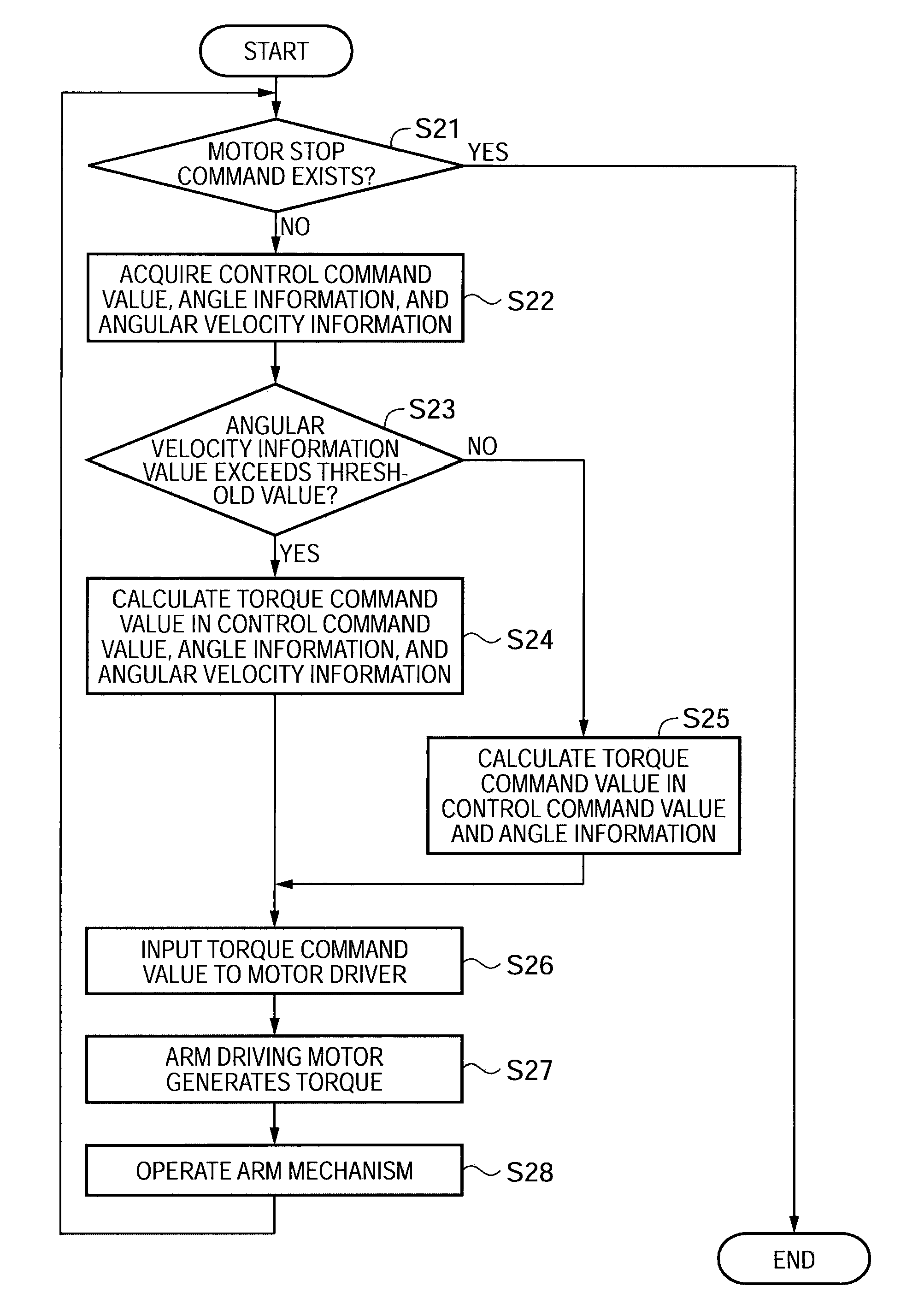
[0081]A first embodiment of a robot, a carriage device and a control method using an inertia sensor will now be described. In this embodiment, a feeding / releasing material device which is an example of the carriage device will be described by way of an example. For example, in a process of fabricating a semiconductor device, the feeding / releasing material device of the embodiment is a feeding / releasing material device capable of treating a wafer on which a plurality of semiconductor chips constituting a semiconductor device is compartment-formed.
Feeding / Releasing Material Device
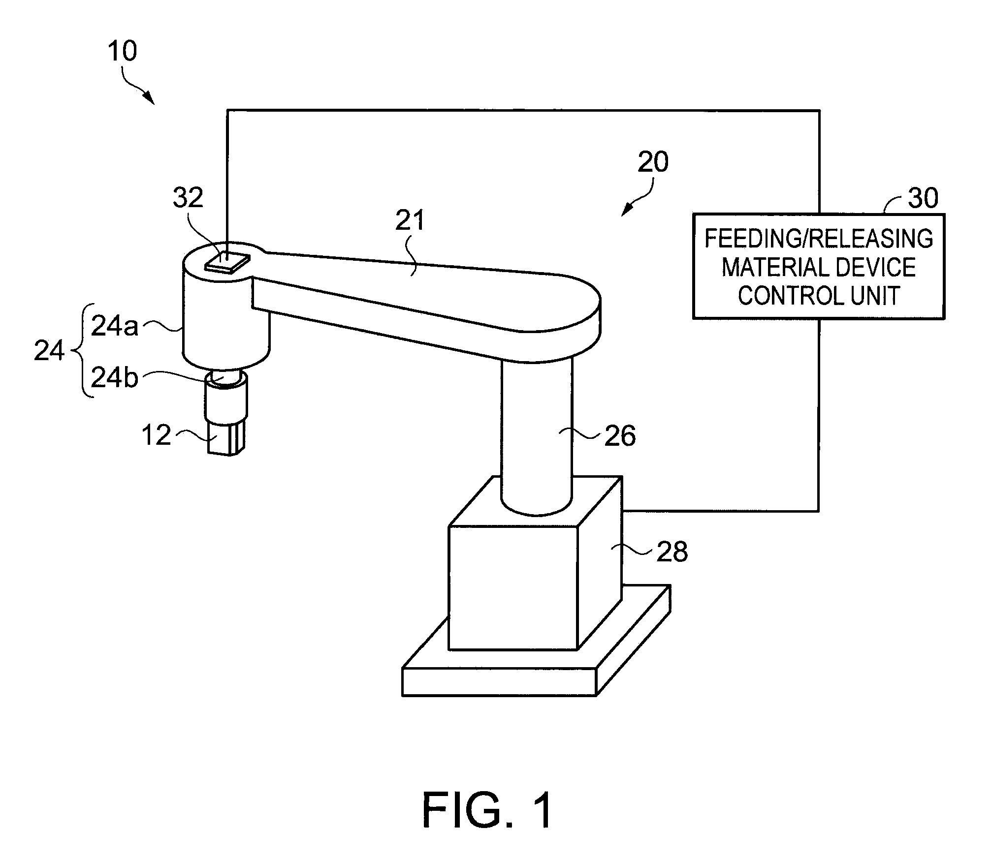
[0082]First, the mechanical configuration of a feeding / releasing material device 10 will be described with reference to FIG. 1. FIG. 1 is a perspective view schematically illustrating an external configuration of the feeding / releasing material device.
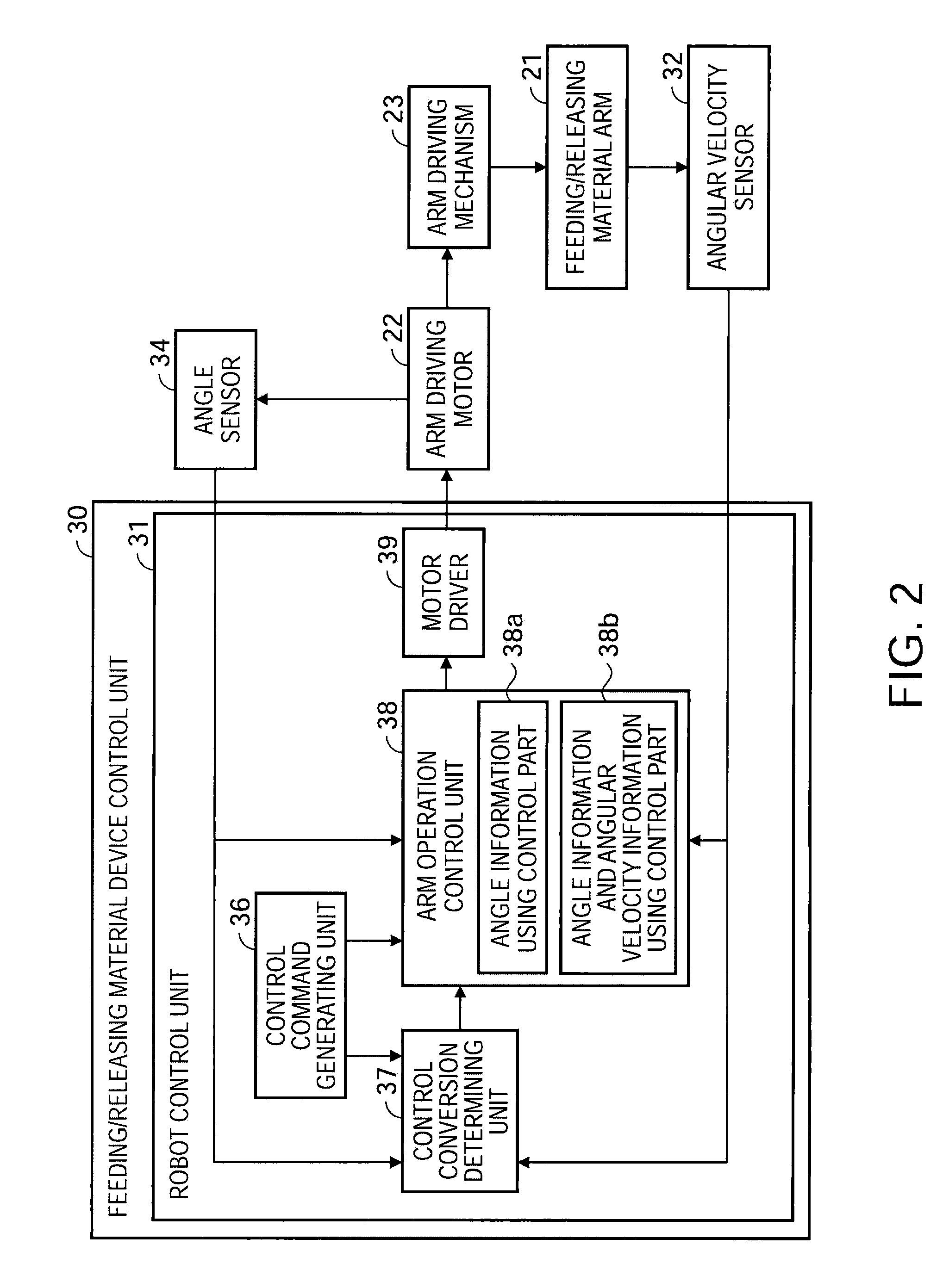
[0083]As shown in FIG. 1, the feeding / releasing material device 10 includes a holding hand 12, a robot mechanism 20, a feeding / releasing material device control ...
embodiment 2
[0118]A second embodiment of a robot, a carriage device and a control method using an inertia sensor will now be described. In this embodiment, a feeding / releasing material device 210 which is an example of the carriage device includes substantially the same mechanical configuration as that of the feeding / releasing material device 10 which is described by reference to FIG. 1 in the first embodiment. The functional configuration of the robot mechanism drive and the process of pivoting a feeding / releasing material arm 21, which are different from a part of the feeding / releasing material device 10, will be described.
Functional Configuration of Robot Mechanism Drive
[0119]First, the functional configuration of driving the robot mechanism 20 in the feeding / releasing material device 210 according to the embodiment will be described with reference to FIG. 5. FIG. 5 is a block diagram illustrating the functional configuration of driving the robot mechanism.
[0120]Similar to the feeding / releas...
embodiment 3
[0140]Next, the third embodiment will be described as a modified example of the first embodiment and the second embodiment. In this embodiment, it will be described another embodiment of the threshold value which is a criteria to determine whether the angular velocity information is used or not used or to determine a value of the gain, when the torque command value is calculated in the first embodiment or the second embodiment.
PUM
 Abstract
Description
Claims
Application Information
 - R&D
- Intellectual Property
- Life Sciences
- Materials
- Tech Scout
- Unparalleled Data Quality
- Higher Quality Content
- 60% Fewer Hallucinations
Browse by: Latest US Patents, China's latest patents, Technical Efficacy Thesaurus, Application Domain, Technology Topic, Popular Technical Reports.
© 2025 PatSnap. All rights reserved.Legal|Privacy policy|Modern Slavery Act Transparency Statement|Sitemap|About US| Contact US: help@patsnap.com


