
Robot, carriage device, and control method using inertia sensor

a technology of inertia sensor and carriage device, which is applied in the direction of electrical programme control, instrumentation, and transmission mechanism or arm deformation, can solve the problems of high misrepresentation of information by control device, deformation of control device, vibration, etc., and achieves the effect of reducing the effect of noise or the like, increasing the influence of inertial force information error, and reducing the effect of using inertial force information

Active Publication Date: 2010-12-16
SEIKO EPSON CORP
View PDF3 Cites 66 Cited by
  • Summary
  • Abstract
  • Description
  • Claims
  • Application Information

AI Technical Summary

Benefits of technology

[0023]According to the robot of this application example, by comparing the lapse time from the specific point of the control command with the threshold value, it is determined whether the angular velocity information is used or not, or the weighted constant of the angular velocity information is determined. More appropriate control can be performed by using the angular velocity information, as compared with the case in which the angular velocity information is not used. If the angular velocity is reduced, the effect obtained by using the angular velocity information is decreased, and simultaneously, the influence resulted from the error of the angular velocity information by the noise or the like is increased. Since it is determined whether the angular velocity information is used or not or the weighted constant of the angular velocity information is determined, by comparing the lapse time from the specific point of the control command with the threshold value, the operation control of the arm can be performed which increases the effect obtained by using the angular velocity information and reduces the influence resulted from the error of the angular velocity information overall.
[0062]According to the control method using the inertial force of this application example, in the step of determining the control conversion or the step of determining the weighed constant, it is determined whether the inertial force information is used or not, or the weighted constant of the inertial force information is determined by comparing the noise affecting the inertial force information with the threshold value. More appropriate control can be performed by using the inertial force information, as compared with the case in which the inertial force information is not used. However, if the noise affecting the inertial force information is increased, the influence of the error in the inertial force information due to the noise or the like is increased, and thus the effect obtained by using the inertial force information is decreased. Since it is determined whether the inertial force information is used or not, or the weighted constant of the inertial force information is determined, by comparing the noise affecting the inertial force information with the threshold value, the moving operation of the movable unit can be controlled which reduces the influence resulted from the error of the inertial force information.

Problems solved by technology

However, since a transmission mechanism for transmitting a driving force to the arm from the driving source or the arm is not made of a rigid body, the transmission mechanism or the arm is deformed.
In addition, there is a problem in that vibration is generated since the transmission mechanism or the arm is deformed upon the operation.
In addition, there is a problem in that if the integration is repeated, it is liable to receive an effect of a drift of a reference potential of the inertia sensor, so that a control device is capable of highly misrecognizing the information.
However, there is a problem in that an error due to the effect of the noise, the effect in delay of signal transmission or the like is possibly contained in the output of the inertia sensor, and thus the control device easily misrecognizes the information due to the error.
Since the effect from the noise of the inertia sensor or the effect from the delay of the signal transmission is a phenomenon which happens even in a high frequency, the control device or the control method disclosed in JP-A-2005-242794 cannot cope with the problem.
However, if the angular velocity is reduced, the effect obtained by using the angular velocity information is decreased, and simultaneously, the influence resulted from the error of the angular velocity information by the noise or the like is obtained.
If the angular velocity is reduced, the effect obtained by using the angular velocity information is decreased, and simultaneously, the influence resulted from the error of the angular velocity information by the noise or the like is increased.
However, if the acceleration is reduced, the effect obtained by using the acceleration information is decreased, and simultaneously, the influence resulted from the error of the acceleration information by the noise or the like is obtained.
However, if the noise affecting the acceleration information is increased, the influence of the error in the acceleration information due to the noise or the like is increased, and thus the effect obtained by using the acceleration information is decreased.
However, if the inertial force is reduced, the effect obtained by using the inertial force information is decreased, and simultaneously, the influence resulted from the error of the inertial force information by the noise or the like is obtained.

Method used


Image

  • Robot, carriage device, and control method using inertia sensor
  • Robot, carriage device, and control method using inertia sensor
  • Robot, carriage device, and control method using inertia sensor

Examples


embodiment 1

[0081]A first embodiment of a robot, a carriage device and a control method using an inertia sensor will now be described. In this embodiment, a feeding / releasing material device which is an example of the carriage device will be described by way of an example. For example, in a process of fabricating a semiconductor device, the feeding / releasing material device of the embodiment is a feeding / releasing material device capable of treating a wafer on which a plurality of semiconductor chips constituting a semiconductor device is compartment-formed.

Feeding / Releasing Material Device

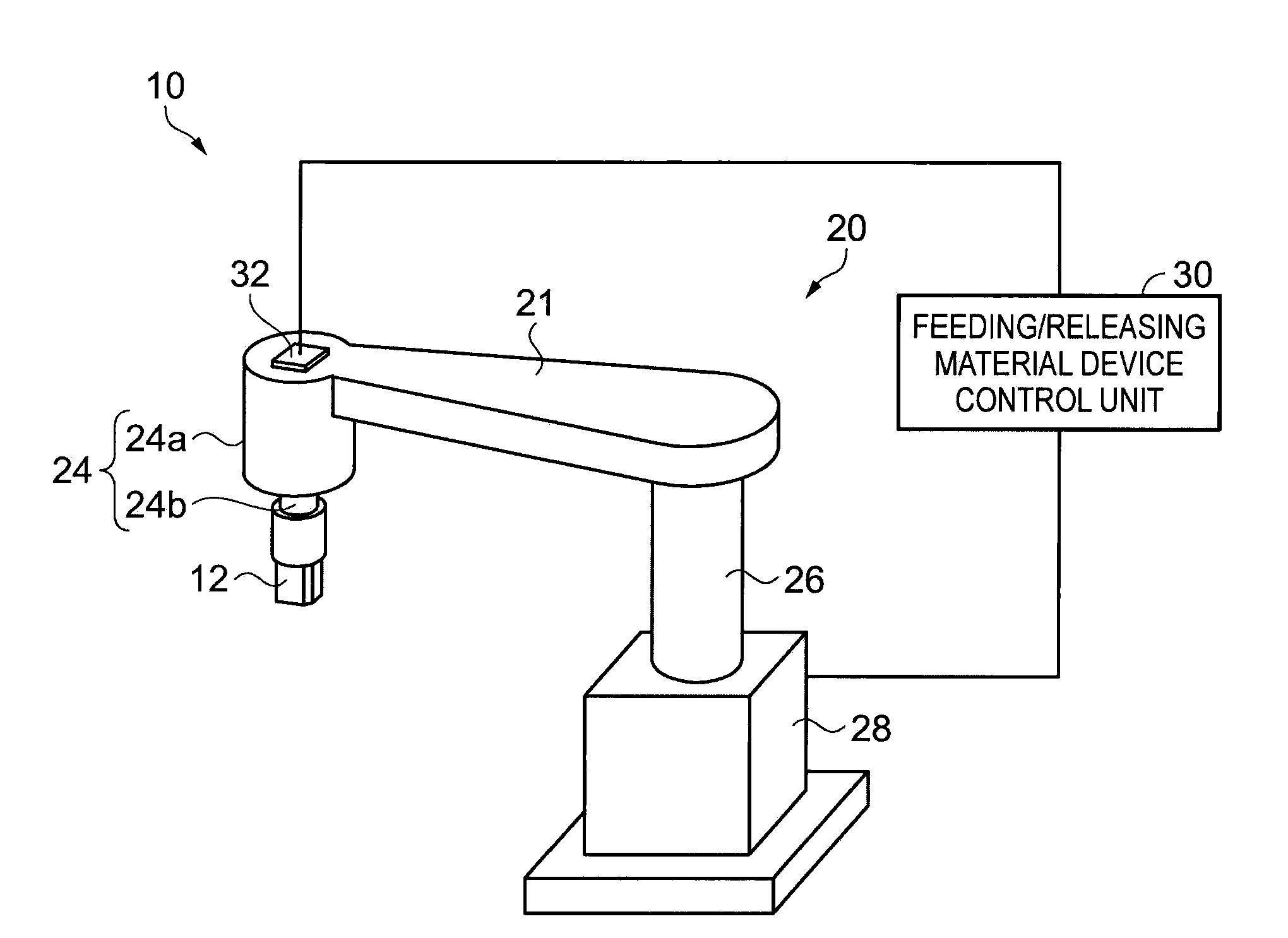
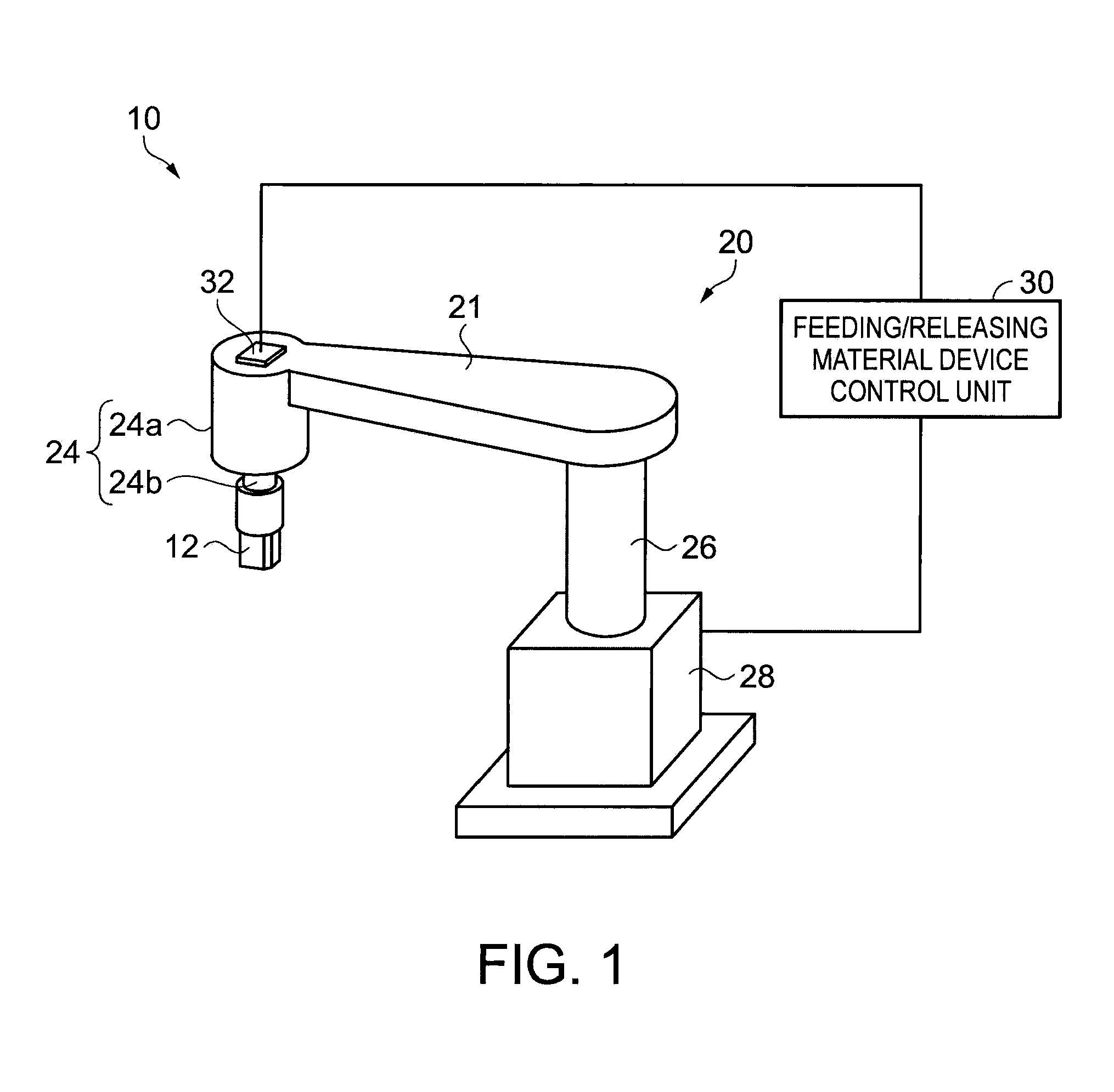
[0082]First, the mechanical configuration of a feeding / releasing material device 10 will be described with reference to FIG. 1. FIG. 1 is a perspective view schematically illustrating an external configuration of the feeding / releasing material device.

[0083]As shown in FIG. 1, the feeding / releasing material device 10 includes a holding hand 12, a robot mechanism 20, a feeding / releasing material device control ...

embodiment 2

[0118]A second embodiment of a robot, a carriage device and a control method using an inertia sensor will now be described. In this embodiment, a feeding / releasing material device 210 which is an example of the carriage device includes substantially the same mechanical configuration as that of the feeding / releasing material device 10 which is described by reference to FIG. 1 in the first embodiment. The functional configuration of the robot mechanism drive and the process of pivoting a feeding / releasing material arm 21, which are different from a part of the feeding / releasing material device 10, will be described.

Functional Configuration of Robot Mechanism Drive

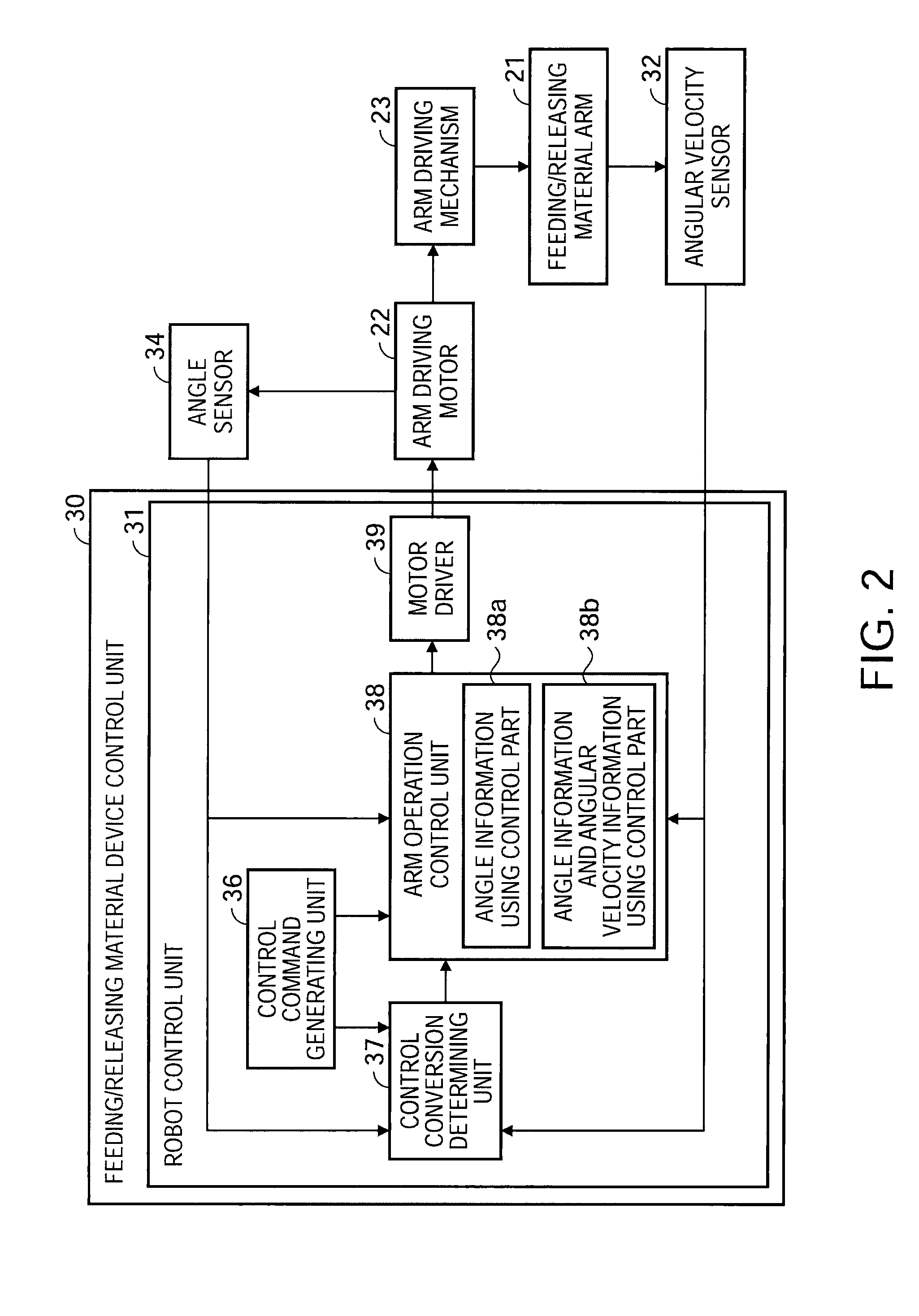
[0119]First, the functional configuration of driving the robot mechanism 20 in the feeding / releasing material device 210 according to the embodiment will be described with reference to FIG. 5. FIG. 5 is a block diagram illustrating the functional configuration of driving the robot mechanism.

[0120]Similar to the feeding / releas...

embodiment 3

[0140]Next, the third embodiment will be described as a modified example of the first embodiment and the second embodiment. In this embodiment, it will be described another embodiment of the threshold value which is a criteria to determine whether the angular velocity information is used or not used or to determine a value of the gain, when the torque command value is calculated in the first embodiment or the second embodiment.


PUM


Abstract

A robot includes: an arm with one end pivotally supported; a driving source that pivots the arm; an angle sensor that detects a pivot angle of the driving source and outputs pivot angle information of the driving source; an inertia sensor that is attached to the arm and outputs inertial force information of an inertial force acting on the arm; a control command generating unit that outputs a control command defining rotational operation of the arm; a control conversion determining unit that determines whether the inertial force information is used or not when the driving source is controlled to control operation of the arm; and an arm operation control unit that performs a first control based on the control command, the pivot angle information, and the inertial force information, to control the driving source and thus control the operation of the arm, if the control conversion determining unit determines to use the inertial force information, and performs a second control which is different from the first control, based on the control command and the pivot angle information, to control the driving source and thus control the operation of the arm, if the control conversion determining unit determines not to use the inertial force information.

Description

BACKGROUND[0001]1. Technical Field[0002]The present invention relates to a robot capable of moving a terminal device, which is attached to a front end of an arm, to a wanted position, a carriage device capable of moving the terminal device, which is attached to the movable member, to a wanted position, and a control method using an inertia sensor to control these devices.[0003]2. Related Art[0004]In the past, it has been widely known an apparatus such as a robot capable of moving a terminal device, which is attached to a front end of an arm by pivoting the arm and so on, to a wanted position and operating the terminal device at the position. For example, there are known a feeding / releasing material device having a gripping terminal and feeding and releasing a matching target part to and from a machining apparatus, an applicator robot having an applicator terminal, a welding robot having a welding terminal or the like.[0005]When the robot is driven, a control method is used, in which...

Claims


Application Information

Patent Timeline
Patent Type & Authority Applications(United States)
IPC IPC(8): G05B15/00
CPCB25J9/1638G05B2219/39195G05B2219/41128G05B2219/42104B25J9/1633B25J9/1651Y10S901/09Y10S901/46G05B2219/42225
Inventor MOTOYOSHI, MASAKIIIDA, IZUMI
Owner SEIKO EPSON CORP
Learn More