Method and apparatus for lubricating a differential gear assembly

a technology of differential gear assembly and lubricating method, which is applied in the direction of gear lubrication/cooling, control devices, vehicle components, etc., can solve the problems of increased gear tooth wear, premature gear failure, and inter-axle differential components being susceptible to torsional driveline vibrations

Active Publication Date: 2005-12-08
ARVINMERITOR TECH
View PDF5 Cites 38 Cited by
  • Summary
  • Abstract
  • Description
  • Claims
  • Application Information

AI Technical Summary

Benefits of technology

[0014] The formation of a channel in a gear body for a side gear provides a simple method and apparatus for providing lubricating fluid to a differential gear assembly

Problems solved by technology

If an inadequate amount of lubricating fluid is provided, overheating can occur, which can significantly increase gear tooth wear or can lead to premature gear failures.
Due to the unique configuration of the tandem drive axle, inter-axle differential components are susceptible to torsional driveline vibrations.
These torsional driveline vibr

Method used


Image

  • Method and apparatus for lubricating a differential gear assembly
  • Method and apparatus for lubricating a differential gear assembly
  • Method and apparatus for lubricating a differential gear assembly

Examples


Embodiment Construction

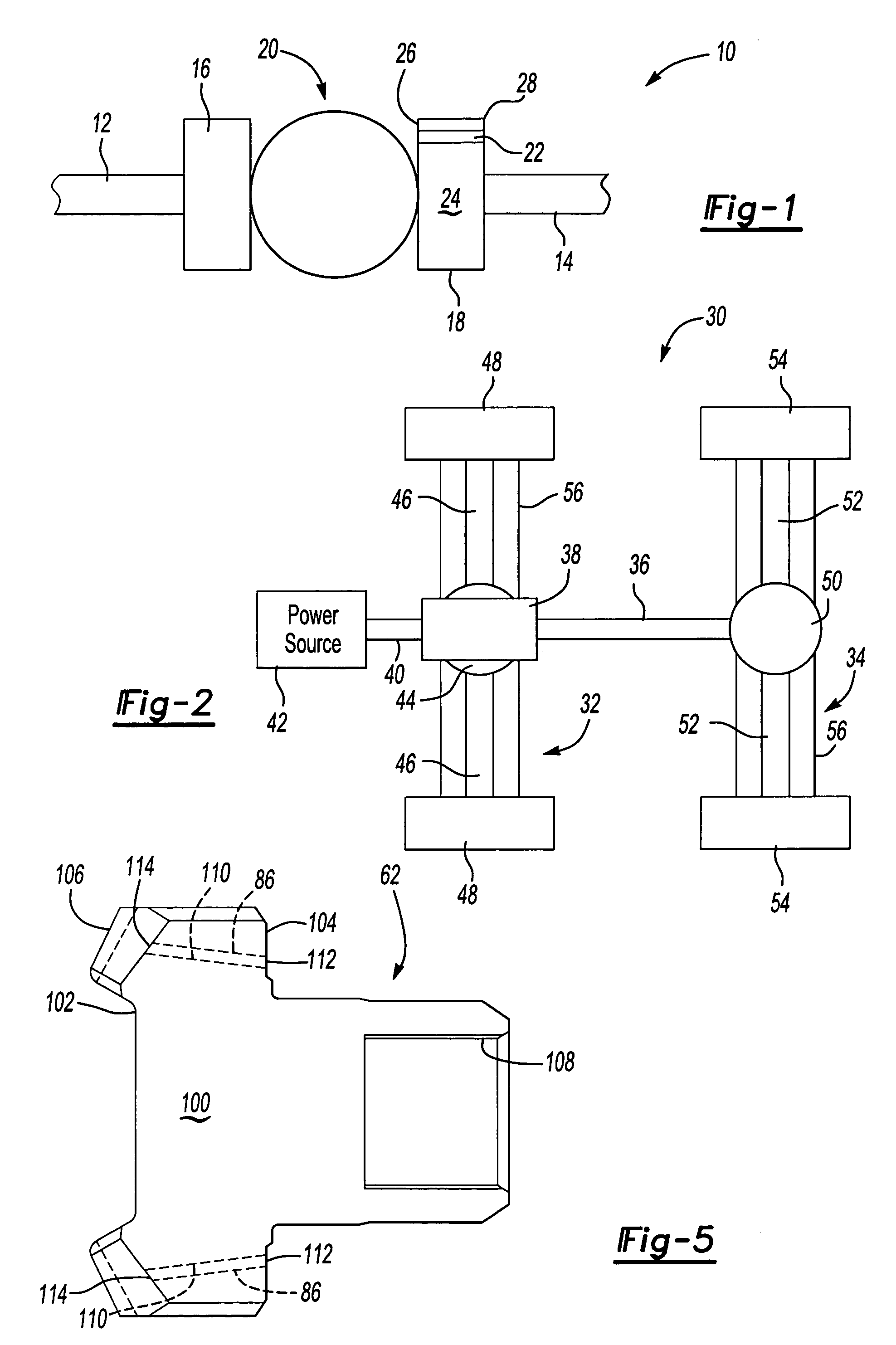
[0021] A differential gear assembly 10, shown in FIG. 1, is used to provide speed differentiation between a first shaft 12 and a second shaft 14. The differential gear assembly 10 includes a first side gear 16, a second side gear 18, and a plurality of differential pinion gears, shown schematically at 20. The differential pinion gears 20 are in meshing engagement with the first 16 and second 18 side gears. The first 16 and second 18 side gears and differential pinion gears 20 interact with each other to provide shaft speed differentiation as needed. The interaction between the first 16 and second 18 side gears and the differential pinion gears 20 to achieve speed differentiation is well known and will not be described in further detail.

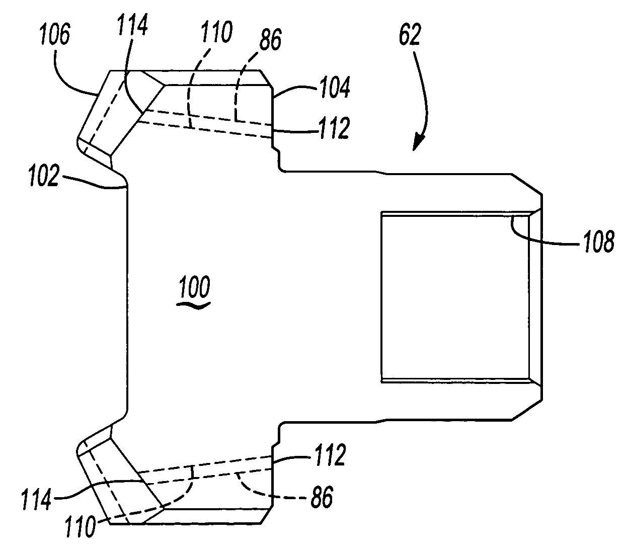
[0022] In order to provide proper lubrication to mating gear teeth contact surfaces between the differential pinion gears 20 and the first 16 and second 18 side gears, at least one channel 22 is formed within the second side gear 18. The second side ...


PUM


Abstract

An inter-axle differential gear assembly includes a first side gear driven by an input shaft, a plurality of inter-axle differential pinion gears in meshing engagement with the first side gear, and a second side gear in meshing engagement with the inter-axle differential pinion gears. The second side gear includes a gear body having a front face and a rear face positioned opposite of the front face. At least one channel, formed within the gear body, extends between the front and rear faces. Lubricating fluid is pumped through the channel to lubricate the inter-axle differential gear assembly. A tapered roller bearing is positioned adjacent the rear face of the second side gear. A seal, positioned between the tapered roller bearing and the rear face of the second side gear, forms a sealed fluid cavity. Rotation of the tapered roller bearing generates a pumping action that pumps the lubricating fluid through the tapered roller bearing, into the sealed fluid cavity, and into the channel.

Description

TECHNICAL FIELD [0001] The subject invention relates to a differential gear assembly with a side gear that includes at least one channel for directing lubricating fluid to the differential gear assembly. BACKGROUND OF THE INVENTION [0002] Drive axle assemblies traditionally include a differential gear assembly that allows speed differentiation between a pair of shafts. For example, the use of the differential gear assembly in a traditional drive axle configuration allows an outer wheel end to rotate at a faster speed than an inner wheel end as a vehicle negotiates through a turning maneuver. The differential gear assembly includes a first side gear, a second side gear, and a plurality of differential pinion gears that are in meshing engagement with the first and second side gears. The first and second side gears and differential pinion gears interact with each other to provide shaft speed differentiation as needed. [0003] Differential gear assemblies can be used in single drive axle...

Claims


Application Information

Patent Timeline
IPC IPC(8): F16H57/04B60K17/16
CPCB60K17/165F16H57/0431F16H57/0483
Inventor OATES, JACK DARRIN
Owner ARVINMERITOR TECH
Why Eureka
Try Eureka