Anatomical shoulder pulley system

a shoulder pulley and anatomical technology, applied in the field of anatomical shoulder pulley systems, can solve the problems of inconvenient adjustment, high cost, and disadvantage of simple pulley systems, and achieve the effect of convenient adjustmen

Inactive Publication Date: 2005-12-08
GUSTAFSON NORMAN PAUL
View PDF12 Cites 13 Cited by
  • Summary
  • Abstract
  • Description
  • Claims
  • Application Information

AI Technical Summary

Benefits of technology

[0005] Accordingly, it is an object of the current invention to provide a device that can assist a person with shoulder movement through the range of motion.
[0006] It is a further object of the invention to provide a device that is capable of assisting shoulder motion in an arc that approximates anatomical motion.
[0007] It is a further object of the current invention to provide a device that can assist a person with forward flexion shoulder movement.
[0008] It is another object of the invention to provide a device that can be easily adjusted to assist with motion in planes other than forward flexion such as internal and external rotation and scapular plane elevation.
[0009] To accomplish these objectives, the device consists of a door unit that provides a base for the device that can be secured to any standard sized door. The door unit includes hardware for securing the unit to a door. There is a mating projection of cylindrical shape that projects outward toward the user from the door u

Problems solved by technology

While these systems are effective in lifting the injured shoulder upward, they have the disadvantage of using linear forces (the straight angle pull of the rope) to produce rotary motion.
This is problematic for the user as a linear upward force produces a force that translates the humerus upward

Method used


Image

  • Anatomical shoulder pulley system
  • Anatomical shoulder pulley system
  • Anatomical shoulder pulley system

Examples


Embodiment Construction

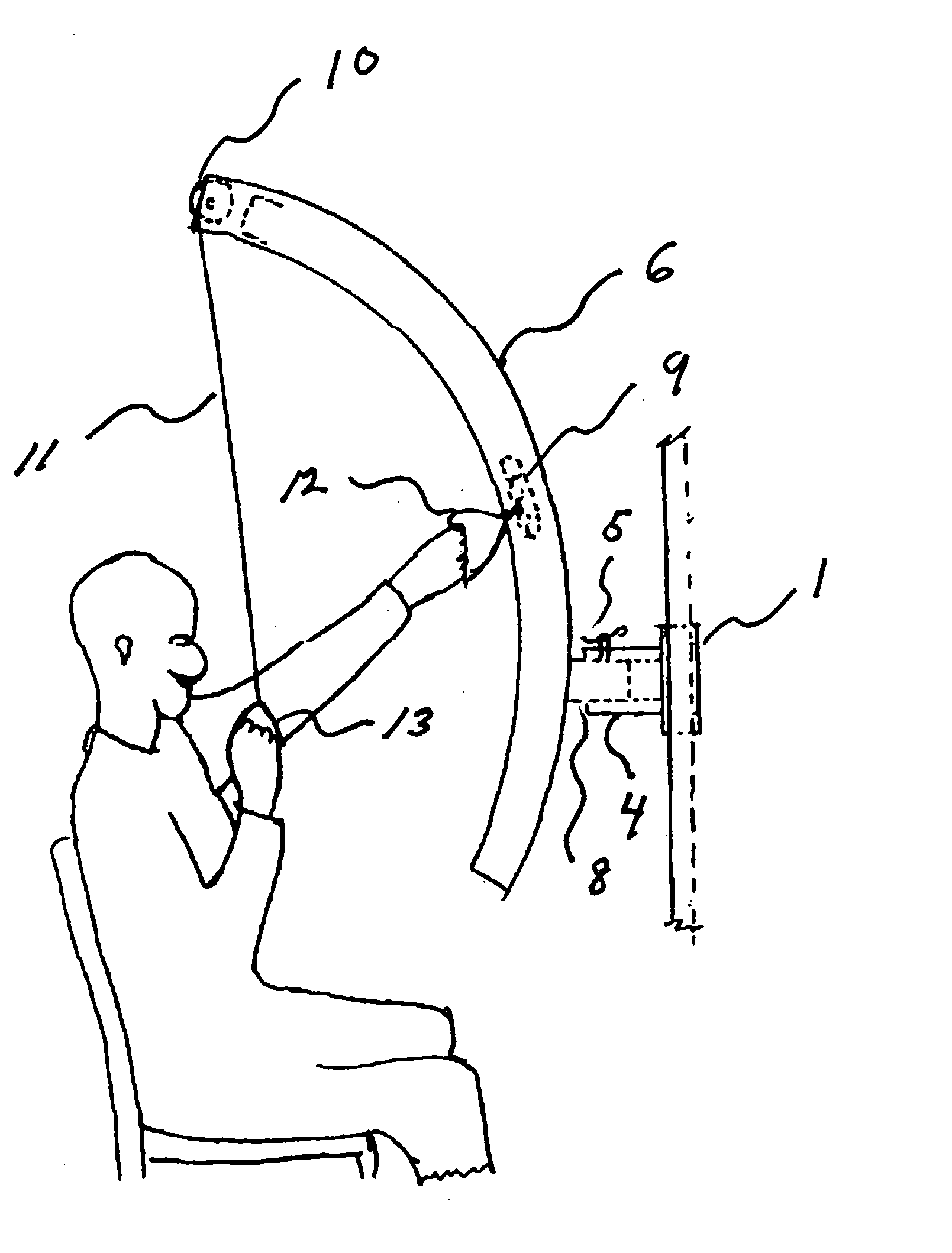
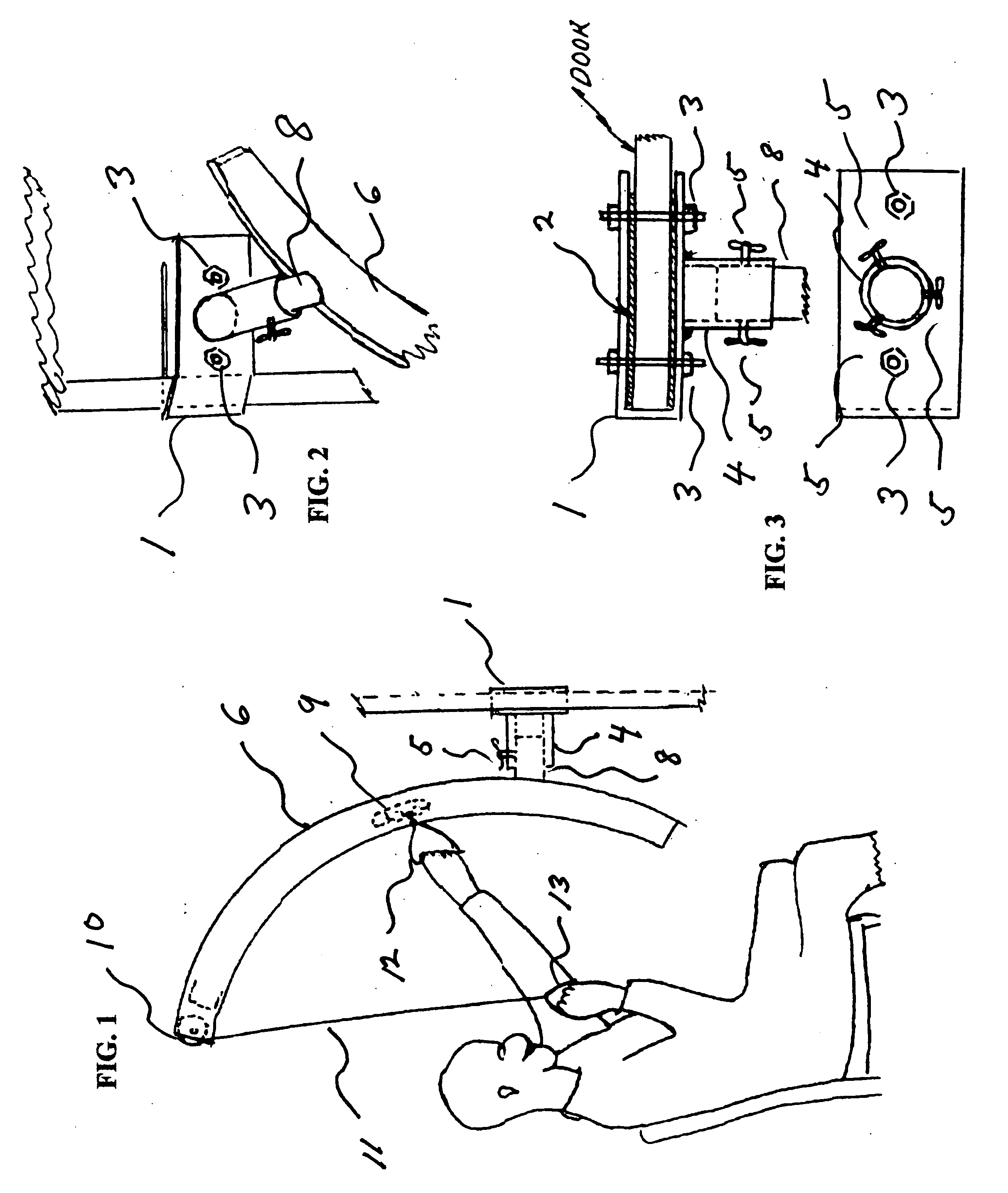
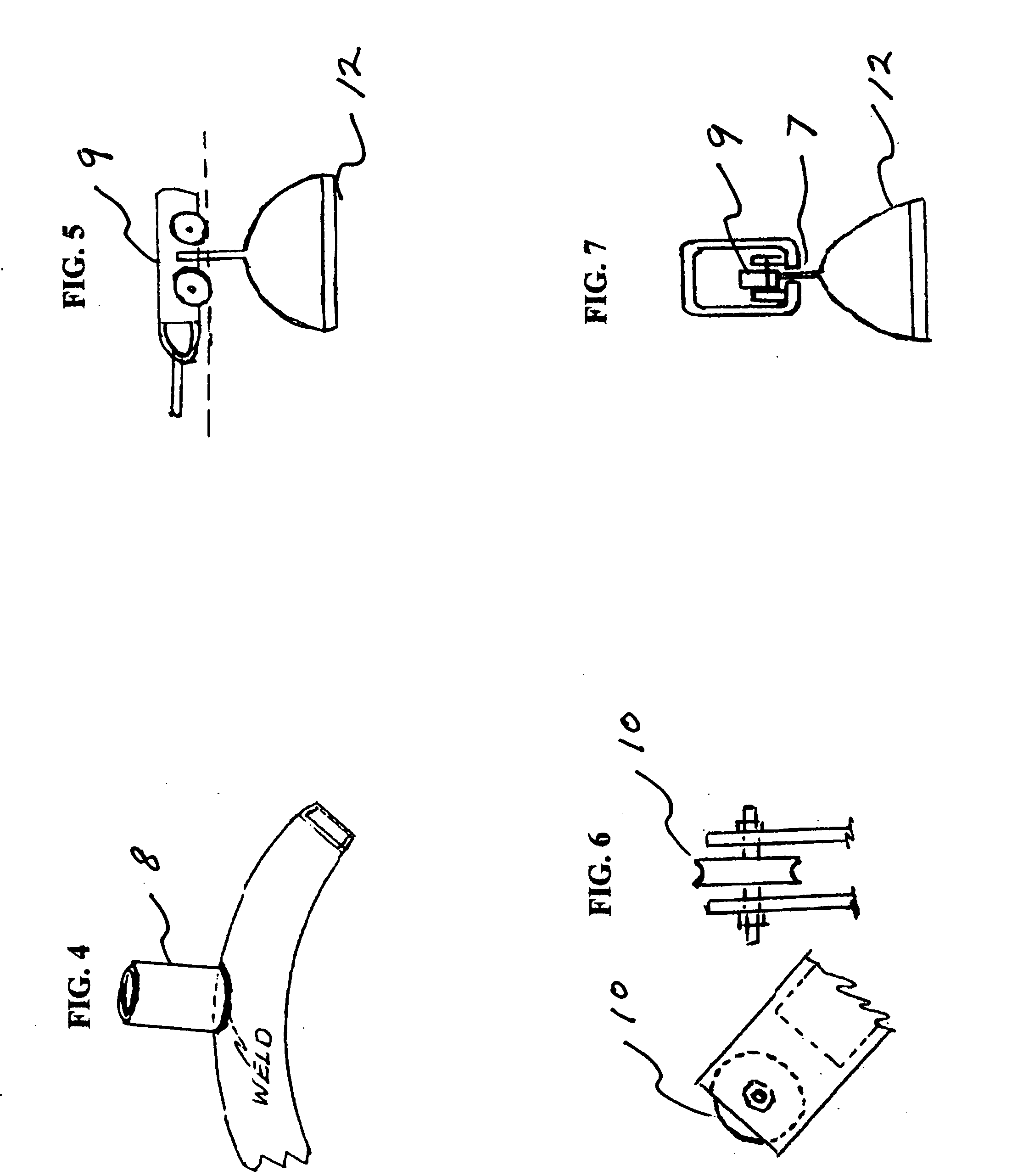
[0017] With reference to figures one through seven there is shown a typical embodiment of the current invention. A door unit 1 is in a “C” channel shape such that it fits over the width of a standard door. A door unit foam liner 2 is included on the inside of the door unit. Door unit bolts 3 are included for secure fastening of the door unit 1 to a standard door. A mating projection on door unit 4 projects outward from the door unit towards the user. Mating projection unit wing bolts 5 thread through the mating unit projection on door unit 4. A second section of the invention consists of an arced track 6 and components associated with it. The arced track is tubular and the shape of the arc is configured to approximate the arc described by a person's shoulder during shoulder flexion, abduction, etc. Along the length of the arced track is a slot in arced track 7. A mating projection on arced track 8 projects outward from the arced track and fits inside the mating projection on door un...


PUM


Abstract

An anatomical shoulder pulley system for use in the rehabilitation of various shoulder conditions. The device provides a means of converting the linear pull of a rope and pulley system into rotary motion that approximates the arc described by anatomical or physiological motion of the shoulder. The device can be adjusted to provide passive or assisted motion in varied planes of shoulder motion such as forward flexion, external or internal rotation or scapular plane shoulder elevation. A door unit section of the device secures the device to a standard door and provides a base for the device. Another section of the device consists of an arced track and associated components. The arced track may be secured to the door unit in varied degrees of rotation. A rope with a handle on one end is routed over a pulley located at the top of the arced track. The other end of the rope is attached to a track rider that can easily move upward and downward within the arced track. A rope and handle are also attached to the track rider. The user grasps both handles. By pulling down on the free end handle, the handle attached to the arced track moves upward along the track assisting a person to move their shoulder in an arc that approximates anatomical or physiological movement.

Description

BACKGROUND—FIELD OF INVENTION [0001] This invention relates to a device that can be used in shoulder rehabilitation to assist a person's shoulder movement in an arc that approximates the arc that is produced during active, non assisted motion. BACKGROUND—DESCRIPTION OF PRIOR ART [0002] There are many shoulder injuries, surgeries or other conditions that require rehabilitation. Rotator cuff injuries, humeral fractures, and frozen shoulder are among this category. During the rehabilitation phase of these conditions it is often beneficial for the injured person to perform passive or assisted motion when they are not capable of performing full active range of motion. Passive or assisted range of motion has the positive affect of maintaining joint structure integrity and maintaining or restoring the proper length of muscles and connective tissue structures. [0003] Devices that are known that can accomplish passive or assisted shoulder motion can be grouped into two categories, pulleys th...

Claims


Application Information

Patent Timeline
IPC IPC(8): A63B21/16A61H1/02B32B3/02A63B21/002A63B21/00D04H11/00
CPCA61H1/0281A61H2201/1276A63B21/00178A63B21/00181A63B21/154A63B21/1645
Inventor GUSTAFSON, NORMAN PAUL
Owner GUSTAFSON NORMAN PAUL
Why Eureka
Try Eureka