
Shoulder stabilizing restraint

a shoulder and restraint technology, applied in the field of shoulder stabilization therapy, can solve the problems of shoulder complications, heavy and uncomfortable wear of rigid casts, and relatively laborious and complex application of rigid casts

Active Publication Date: 2005-12-08
BREG
View PDF15 Cites 33 Cited by
  • Summary
  • Abstract
  • Description
  • Claims
  • Application Information

AI Technical Summary

Benefits of technology

[0012] The present invention is a shoulder stabilizing restraint. The shoulder stabilizing restraint includes a pillow which has a forearm engagement face and a vertically-aligned posterior face. The forearm engagement face has a relatively flat configuration for engaging a forearm on a first side of a user (i.e., either the right or the left side of the user). The posterior face has an arcuate configuration having a length of about 90° or less for engaging an anterior qua...

Problems solved by technology

Although the rotational capabilities of the shoulder recited above advantageously enhance the function of the joint, the same expansive rotational capabilities also complicate treatment of the shoulder following injury or surgery.
However, the disadvantages of rigid casts are well known.
Rigid casts are heavy and uncomfortable to wear and are relatively laborious and complex to apply.
Rigid casts may also unduly limit the mobility of the patient and cause joint stiffening and muscle atrophy.
However, such devices are significantly more complex and costly.
The basic stock materials for constructing the devices are relatively expensive and construction of the devices requires molding all of the constituent parts piece by piece from the stock materials while very hot.
Adjusting the fit of the device requires cutting off excess material once the device is in place which can produce sharp edges.
In addition, such devices, like rigid casts, can only be used once.
Support devices using metal components are likewise costly and are also relatively heavy.

Method used


Image

  • Shoulder stabilizing restraint
  • Shoulder stabilizing restraint
  • Shoulder stabilizing restraint

Examples


Embodiment Construction

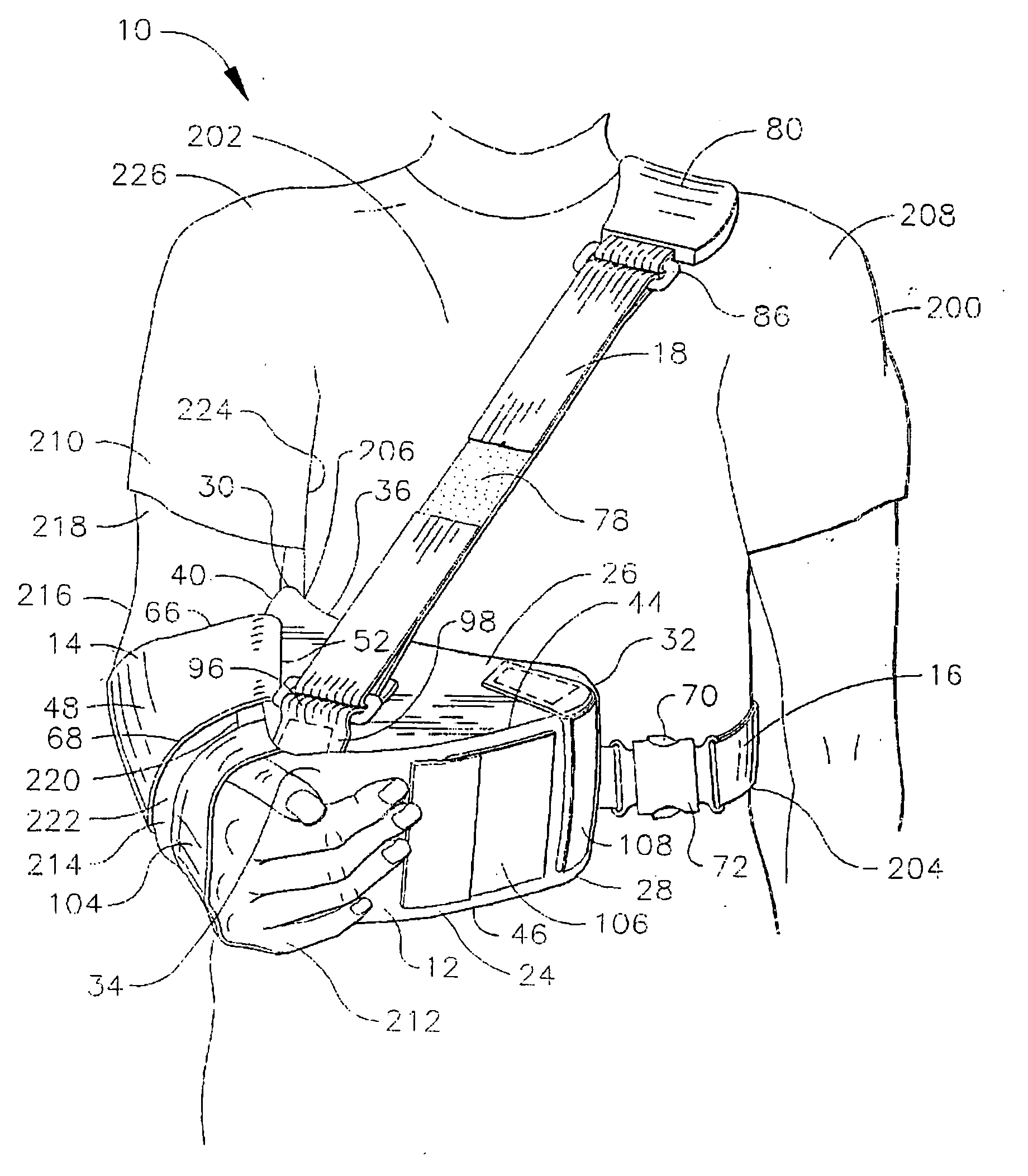
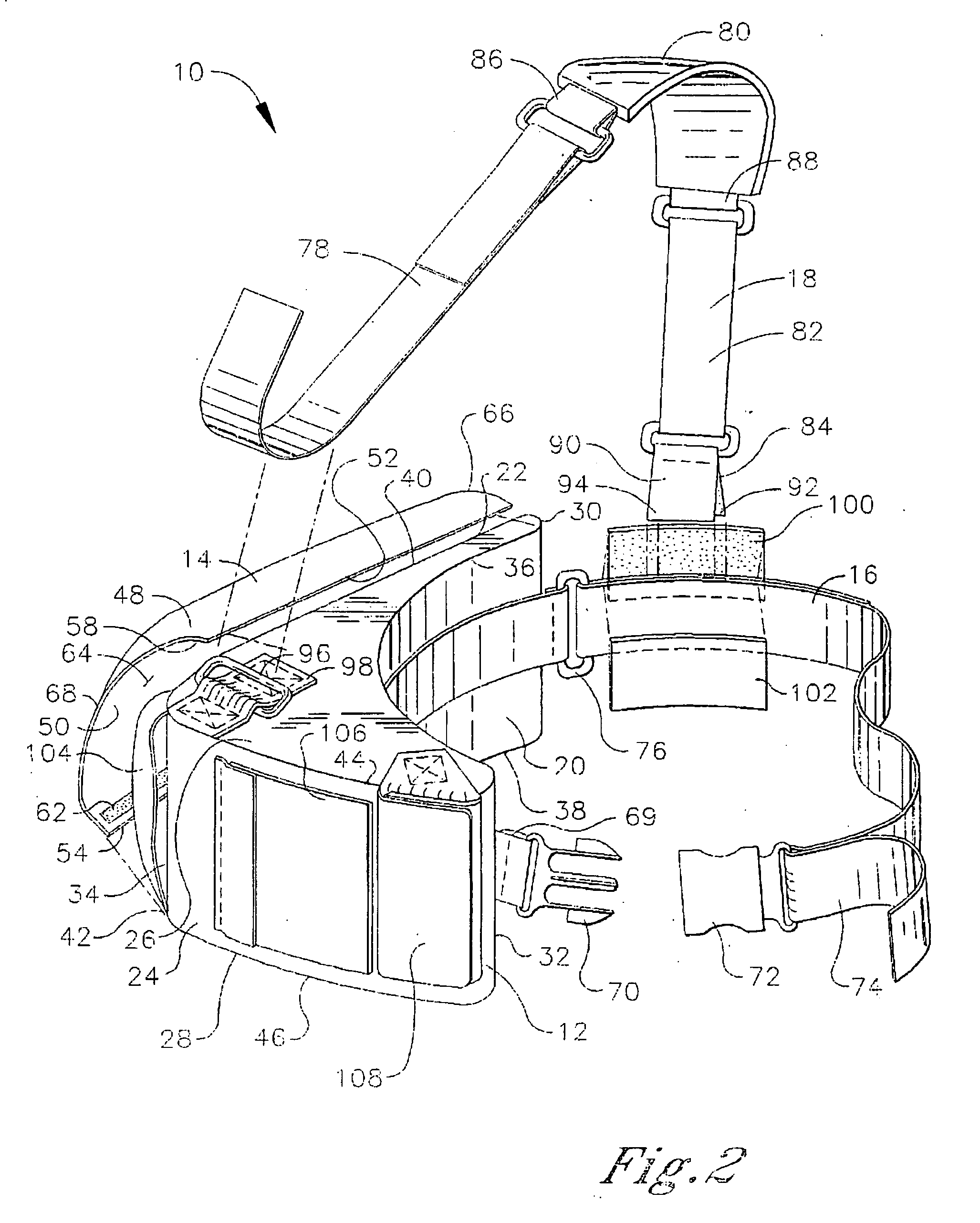
[0028] Referring to FIG. 2, an embodiment of a shoulder stabilizing restraint of the present invention is shown and generally designated 10. The shoulder stabilizing restraint 10 of the present embodiment is configured to restrain and stabilize the right shoulder joint of a user. However, the shoulder stabilizing restraint 10 is readily reconfigured to restrain and stabilize the left shoulder joint of a user in a manner described hereafter. A user is defined herein as an individual on whom the shoulder stabilizing restraint 10 is mounted.

[0029] The shoulder stabilizing restraint 10 comprises a pillow 12, a forearm wrap 14, a waist belt 16, and a shoulder strap 18. In accordance with the present embodiment, the pillow 12 approximates a triangular profile when viewed from above or below. The pillow 12 has a plurality of faces, which are termed in correspondence with their preferred orientation when the shoulder stabilizing restraint 10 is operatively mounted on a user as described he...


PUM


Abstract

A shoulder stabilizing restraint is provided which includes a pillow and a forearm wrap. The pillow has an arcuately-configured posterior face for engaging an anterior quadrant of a torso on a first side of a user. The pillow also has a flat forearm engagement face for engaging a forearm on the first side of the user. The forearm engagement face is preferably converges with the posterior face at a posterior / lateral convergence which is positionable proximal to a lateral border of the torso on the first side of the user. The forearm wrap is fastenable to the pillow to retain the forearm in engagement with the forearm engagement face and the shoulder joint at a positive external rotation angle.

Description

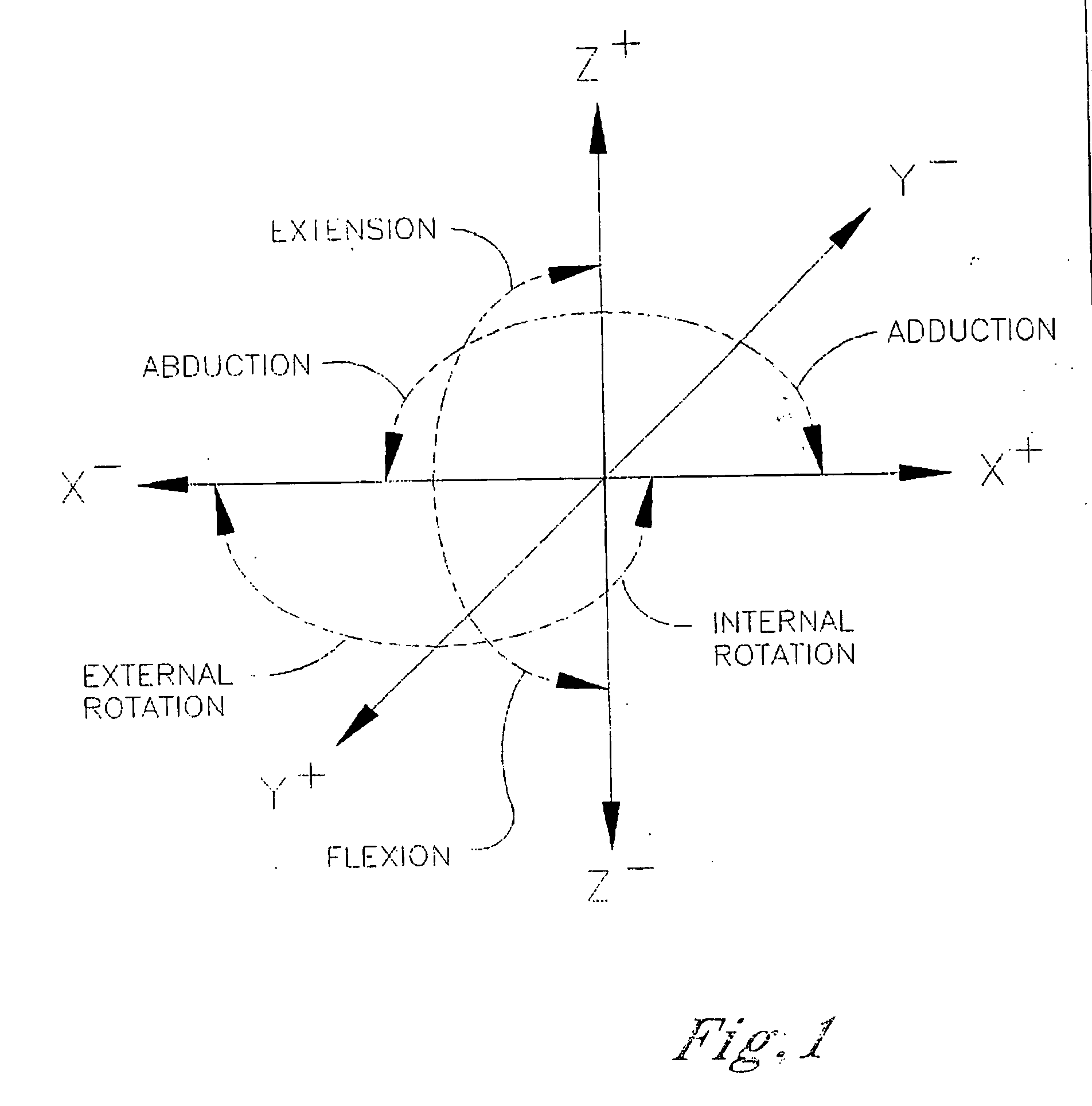
TECHNICAL FIELD [0001] The present invention relates generally to therapeutic stabilization of the shoulder joint, and more particularly to an apparatus for maintaining the shoulder joint in a stable position which facilitates healing of the shoulder joint following an injury or surgery to the joint. BACKGROUND OF THE INVENTION [0002] The shoulder is a relatively complex joint of the body, which is capable of rotation within multiple planes when the arm is displaced relative to the torso. Referring to FIG. 1, the shoulder is rotatable within three different planes of rotation, i.e., an X-Y plane containing the X and Y axes, an X-Z plane containing the X and Z axes, and a Y-Z plane containing the Y and Z axes. The Z axis has a vertical orientation aligning the Z axis in correspondence with the central longitudinal axis of a standing person. The X and Y axes both have a horizontal orientation, being perpendicular to one another and to the Z axis. [0003] When the Z axis corresponds ide...

Claims


Application Information

Patent Timeline
IPC IPC(8): A61F5/37A61F5/00
CPCA61F5/3753
Inventor HOWARD, MARK E.
Owner BREG
Learn More