

Magnetically navigable balloon catheters
a balloon catheter and magnetic technology, applied in the field of balloon catheters, can solve the problems of difficult to direct the catheter into certain areas, difficult to navigate the balloon, and particularly the balloon and the stent, and achieve the effect of reducing the discontinuity of flexibility and facilitating the use of the balloon catheter
- Summary
- Abstract
- Description
- Claims
- Application Information
AI Technical Summary
Benefits of technology
Problems solved by technology
Method used
Image

Examples
first embodiment
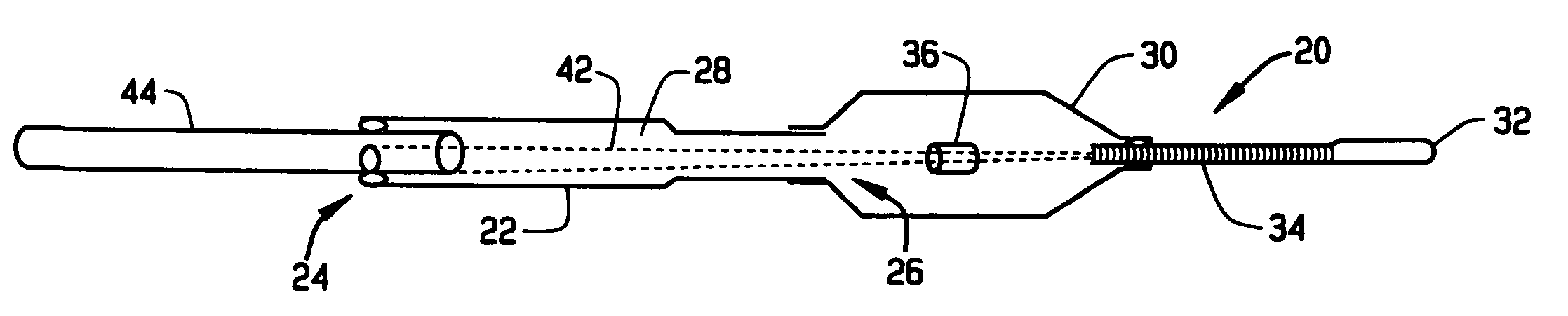
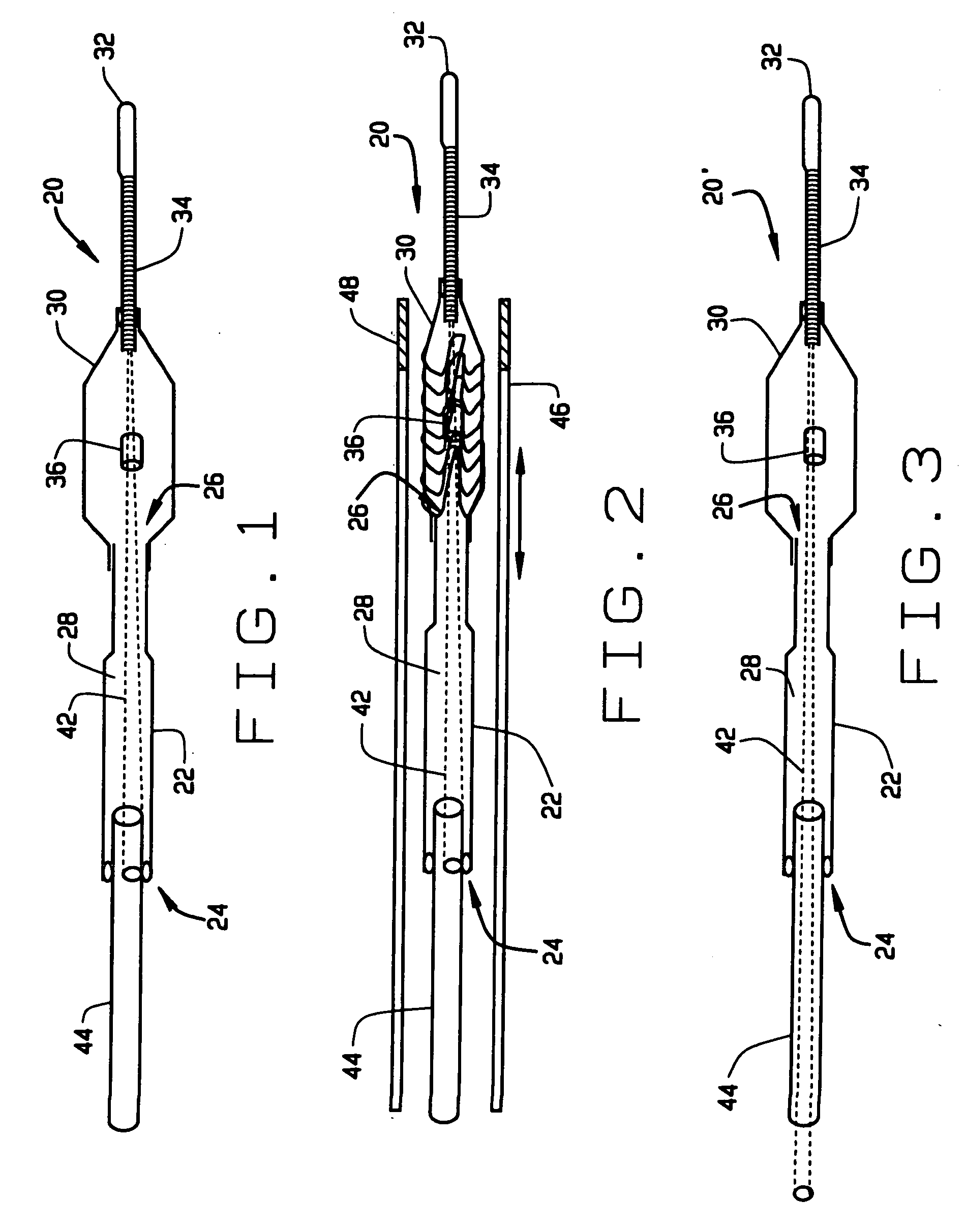
[0035] As shown in FIG. 1, in this first embodiment a flexible, radiopaque element 34 can be provided between the magnetically responsive element 32 and the balloon 30. The radiopaque element 34 is preferably a flexible coil. This coil can be made of a radiopaque material, or it can be a non-radiopaque material coated with a radiopaque material. For example the element 34 could be made of a magnetically permeable material such as hiperco, plated with gold. Making the radiopaque element out of a permeable magnetic material help control and orient the distal end of the balloon 30 in an applied magnetic field. As shown in FIG. 1, the proximal end of the element 34 extends proximally of the distal end of the balloon 30. This overlap helps location of the distal end of the balloon 30 in fluoroscopic images, and if made of a magnetically responsive element, also helps control the distal of the balloon.
[0036] As also shown in FIGS. 1-4, the balloon catheter 20 of this first embodiment pref...
second embodiment
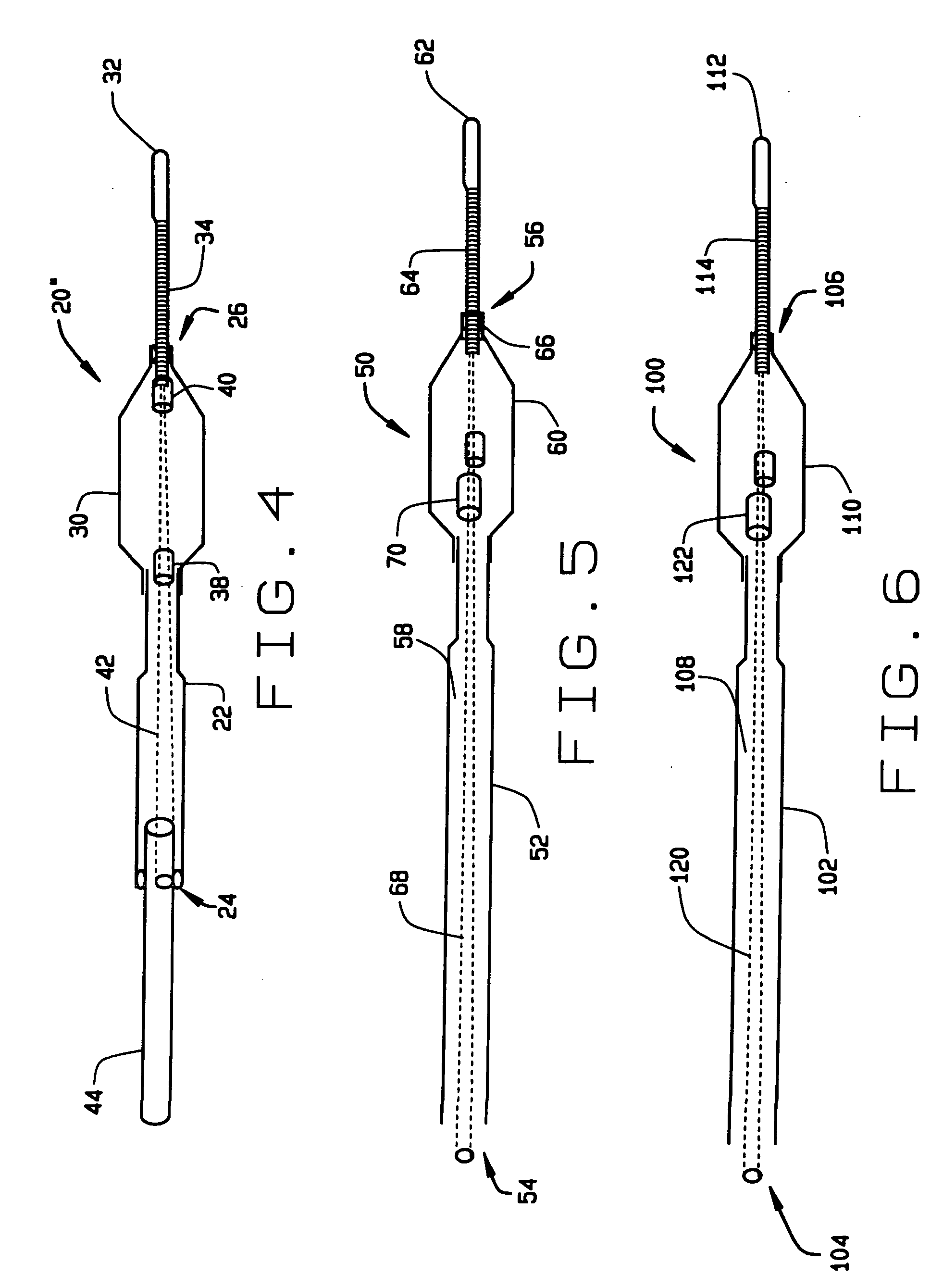
[0043] As shown in FIG. 5, in this second embodiment a flexible, radiopaque element 64 can be provided between the magnetically responsive element 62 and the balloon 60. The radiopaque element 64 is preferably a flexible coil. This coil can be made of a radiopaque material, or it can be a non-radiopaque material coated with a radiopaque material. For example the element 64 could be made of a magnetically permeable material such as hiperco, plated with gold. Making the radiopaque element out of a permeable magnetic material help control and orient the distal end of the balloon 60 in an applied magnetic field. As shown in FIG. 5, a second magnetically responsive element 66 is provided at the proximal end of the element 64, distal to the balloon 60.
[0044] The balloon catheter 50 also includes a core wire 68, disposed inside the balloon catheter. The core wire 68 helps control the stiffness / flexibility of the device, reducing sharp discontinuities in flexibility that could interfere wit...
third embodiment
[0047] As shown in FIG. 6, in this third embodiment a flexible element 114 is provided between the magnet element 112 and the balloon 110, made of a magnetically permeable material such as hiperco. The element 114 can be made radiopaque, for example with gold plating. As shown in FIG. 6, the proximal end of the element 114 extends proximally of the distal end of the balloon 110. This overlap helps control the distal of the balloon, and if element 114 is made of a radiopaque material it helps locate the distal end of the balloon 110 in fluoroscopic images.
[0048] The balloon catheter 100 can also include a core wire. As shown in FIG. 6, a core wire 120 is disposed inside the balloon catheter. The core wire 120 helps control the stiffness / flexibility of the device, reducing sharp discontinuities in flexibility that could interfere with the navigation of the balloon catheter. In this third preferred embodiment, the core wire 120 tapers in the distal direction from a point proximal to th...
PUM
 Abstract
Description
Claims
Application Information