
Audio signal encoding and decoding apparatus

a technology of audio signal and encoding apparatus, which is applied in the direction of speech analysis, track finding/aligning, instruments, etc., can solve the problems of loss of audio signal, increase in bit rate, and inability to compensate for loss of audio signal

Inactive Publication Date: 2005-12-08
SAMSUNG ELECTRONICS CO LTD
View PDF4 Cites 48 Cited by
  • Summary
  • Abstract
  • Description
  • Claims
  • Application Information

AI Technical Summary

Benefits of technology

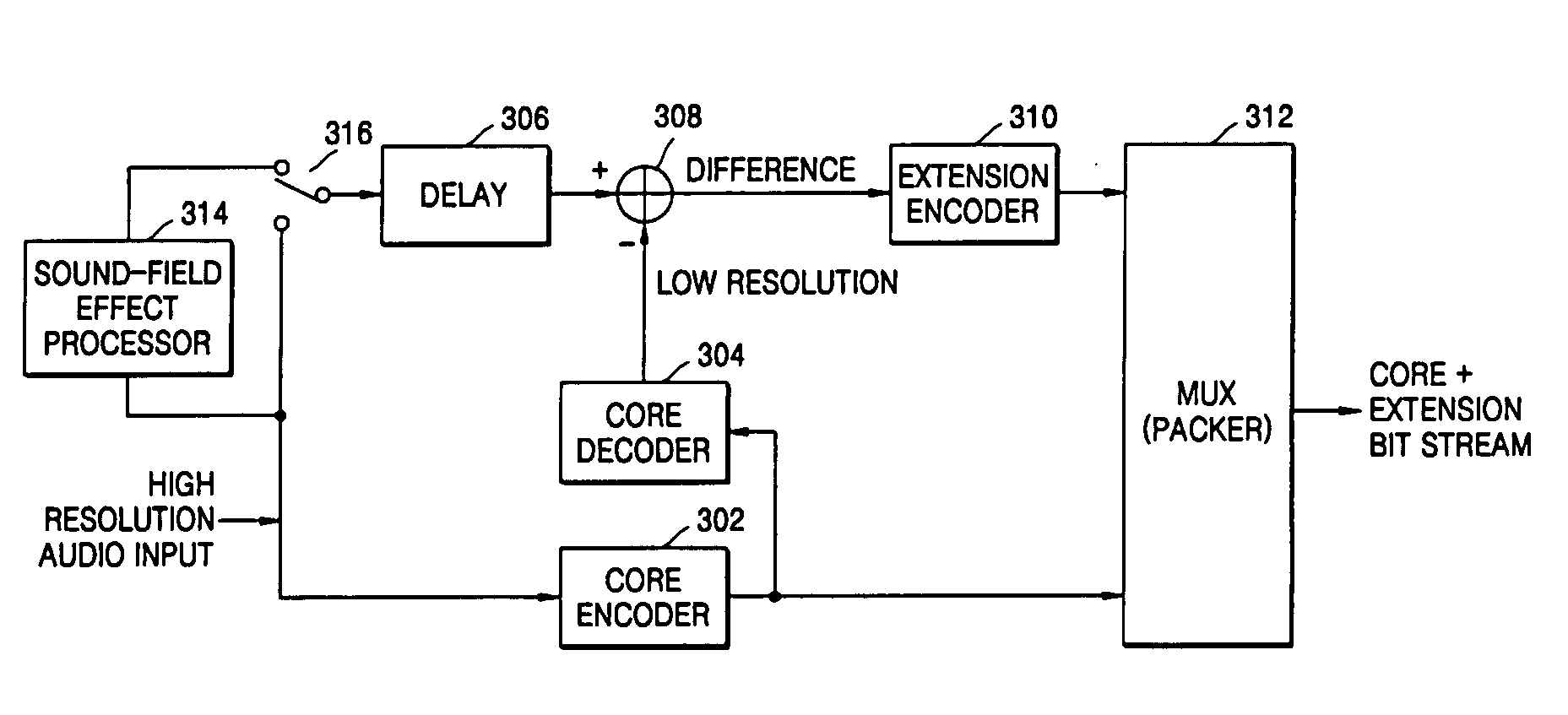
[0024] The foregoing and/or other aspects of the present general inventive concept are achieved by providing an audio signal encoding apparatus capable of transmitting an audio signal or an audio signal together with a sound-field-effect-processed audio signal.
[0025] The audio signal encoding apparatus includes a core encoder to encode an input audio signal according to an audio signal encoding standard, a core decoder to decode the encoded audio signal output from the core encoder, a sound-field-effect processor to perform a sound-field-effect process on the input audio signal, a selector to selectively output one of the input audio signal and the sound-field-effect-processed audio signal output from the sound-field-effect processor, a subtraction unit to calculate a difference signal between the signals output from the core decoder and the selector, an extension encoder to encode the difference signal output from the subtraction unit according to an arbitrary encoding scheme and to output a resultant extension encoded signal, and a multiplexer to multiplex the encoded au...

Problems solved by technology

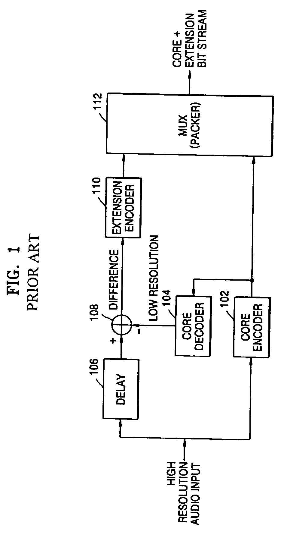
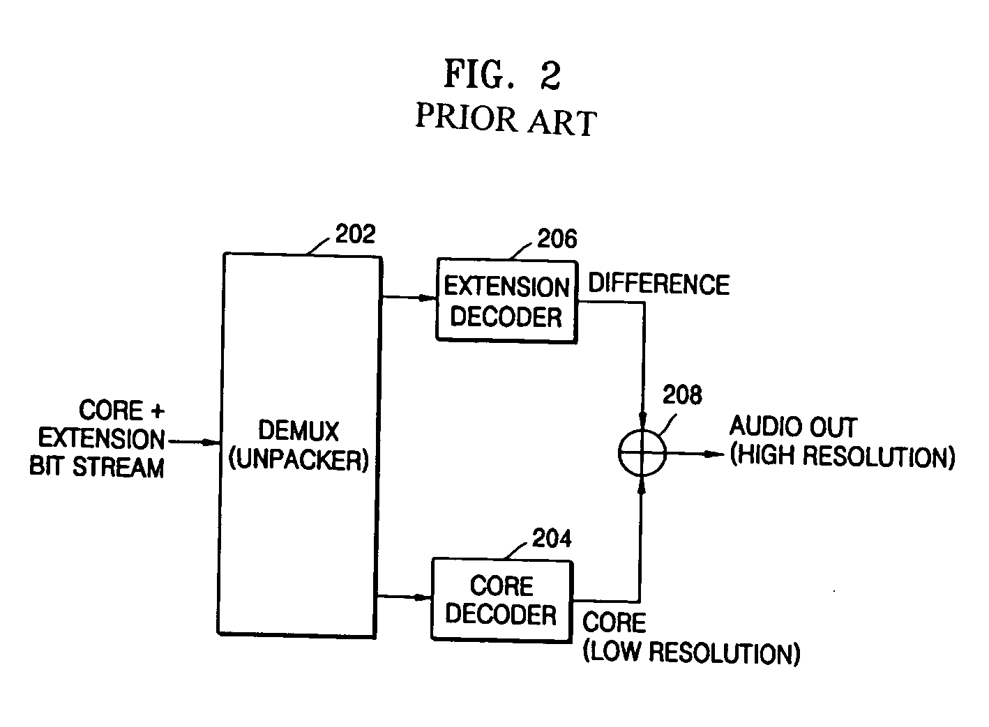
However, these standards have problems in that their encoding processes result in loss of audio signal.
However, since the audio signal has no time correlation, it is impossible to compensate for the loss of audio signal.
However, this method has a serious problem in that the encoding process results in increase in bit rate.

Method used


Image

  • Audio signal encoding and decoding apparatus
  • Audio signal encoding and decoding apparatus
  • Audio signal encoding and decoding apparatus

Examples


Embodiment Construction

[0037] Reference will now be made in detail to the embodiments of the present general inventive concept, examples of which are illustrated in the accompanying drawings, wherein like reference numerals refer to the like elements throughout. The embodiments are described below in order to explain the present general inventive concept while referring to the figures.

[0038]FIG. 3 is a block diagram illustrating an audio signal encoding apparatus according to an embodiment of the present general inventive concept. The audio signal encoding apparatus includes a core encoder 302 to encode an input audio signal according to an audio signal encoding standard, a core decoder 304 to decode the encoded audio signal output from the core encoder 302, a sound-field-effect processor 314 to perform a sound-field-effect process on the input audio signal, a selector 316 to selectively output one of the input audio signal and the sound-field-effect-processed audio signal output from the sound-field-eff...


PUM


Abstract

An audio signal encoding and decoding apparatus capable of transmitting an audio signal or an audio signal together with a sound-field-effect-processed audio signal are provided. The audio signal encoding apparatus includes a core encoder to encode an input audio signal according to an audio signal encoding standard, a core decoder to decode the encoded audio signal output from the core encoder, a sound-field-effect processor to perform a sound-field-effect process on the input audio signal, a selector to selectively output the input audio signal or the sound-field-effect-processed audio signal output from the sound-field-effect processor, a subtraction unit to calculate a difference signal between the signals output from the core decoder and the selector, an extension encoder to encode the difference signal output from the subtraction unit according to an arbitrary encoding scheme and to output the extension encoded signal, and a multiplexer to multiplex the encoded audio signal output from the core encoder and the extension encoded signal output from the extension encoder into a composite encoded signal and to output the composite encoded signal.

Description

CROSS-REFERENCE TO RELATED APPLICATIONS [0001] This application claims the priority under 35 U.S.C. § 119 of U.S. Provisional Patent Application No. 60 / 576,619, filed on Jun. 4, 2004, and U.S. Provisional Patent Application No. 60 / 578,861, filed on Jun. 14, 2004, in the U.S. Patent and Trademark Office, and Korean Patent Application No. 2004-43076, filed on Jun. 11, 2004, in the Korean Intellectual Property Office, the disclosures of which are incorporated herein in their entirety by reference.BACKGROUND OF THE INVENTION [0002] 1. Field of the Invention [0003] The present general inventive concept relates to an audio signal encoding apparatus, and more particularly, to an audio signal encoding and decoding apparatus capable of transmitting an audio signal or an audio signal together with a sound-field-effect-processed audio signal. [0004] 2. Description of the Related Art [0005] Recently, various types of audio signal encoding schemes have been proposed. For example, the Dolby AC3 a...

Claims


Application Information

Patent Timeline
IPC IPC(8): G10L19/14G10L19/00G10L21/02G11B21/10H03M7/00H03M7/30H04S1/00H04S3/00
CPCG10L19/18H04S1/007H04S3/008H04S2400/01H04S2420/01H04S2420/03G10L21/0364
Inventor LEE, HYUCK-JAEPARK, SUNG-WOOKPARK, HAE-KWANG
Owner SAMSUNG ELECTRONICS CO LTD
Learn More