
Key

Inactive Publication Date: 2005-12-15
IRONWORKS PATENTS LLC
View PDF2 Cites 14 Cited by
  • Summary
  • Abstract
  • Description
  • Claims
  • Application Information

AI Technical Summary

Benefits of technology

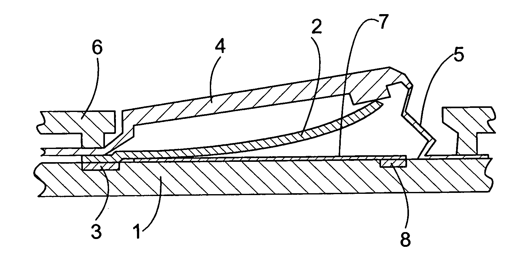
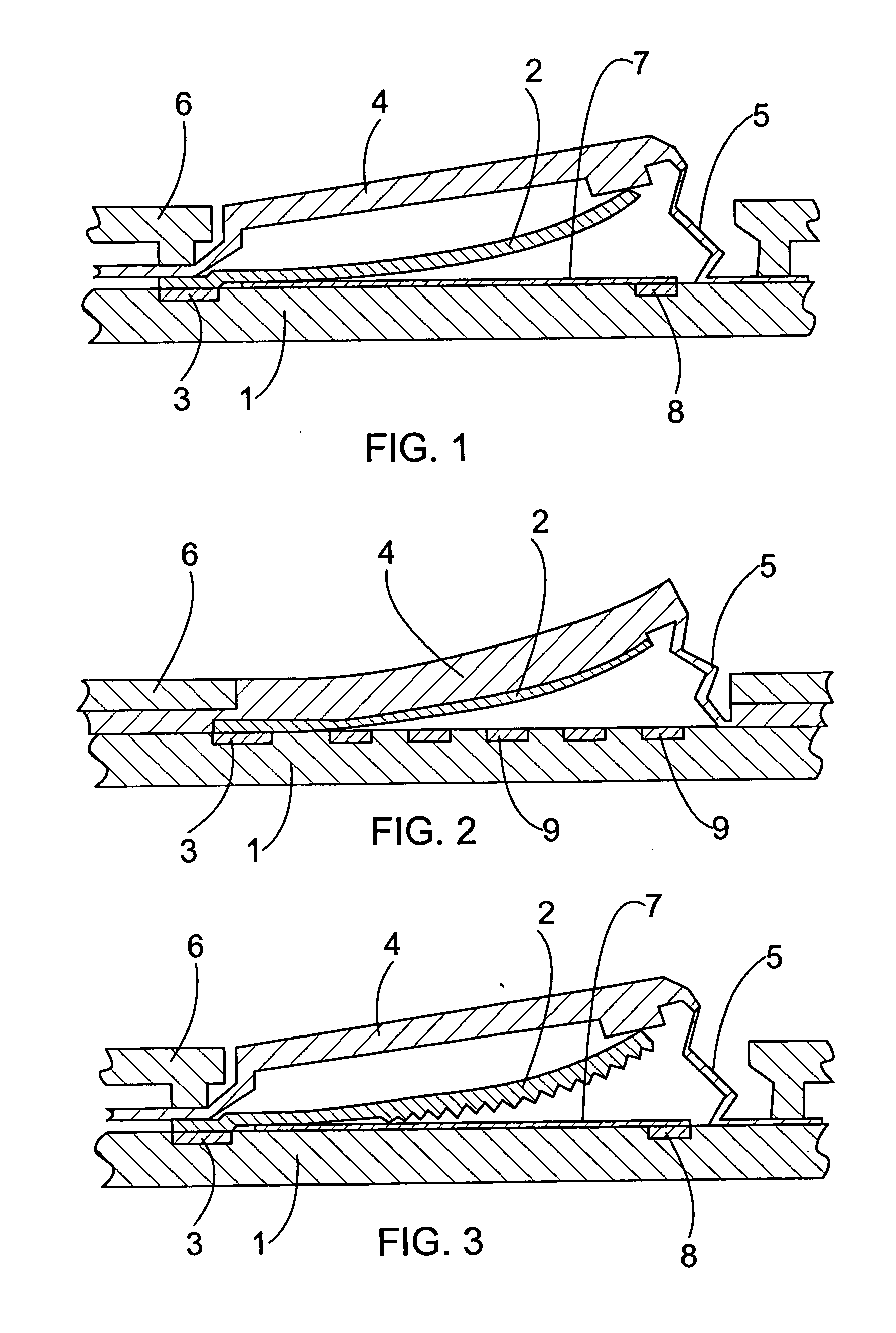
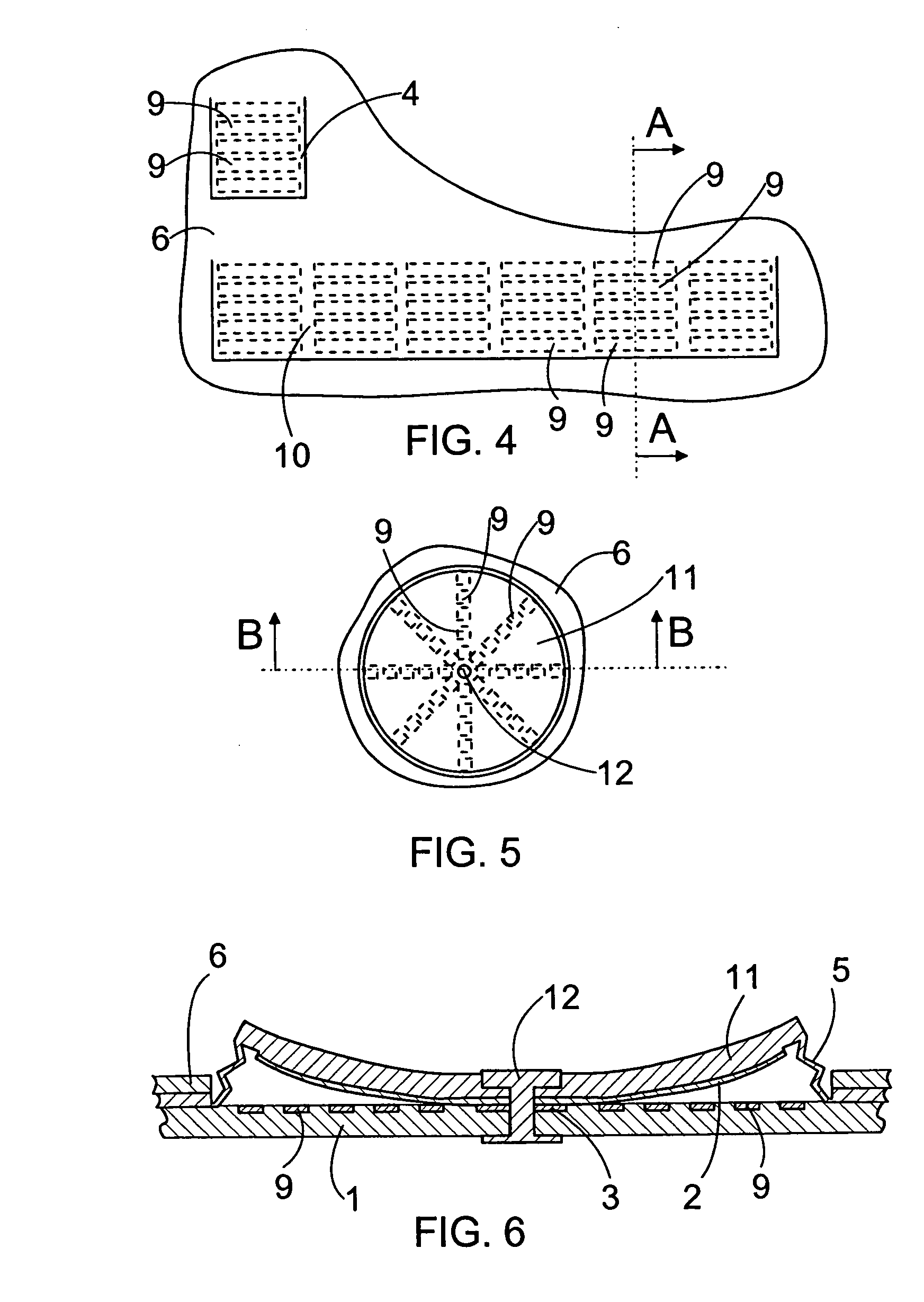
[0007] The essential idea of the invention is that the key has a varying response dependent on the manner of depression and the key comprises at least a base and a switching element arranged curved relative to one another. When the switching element is depressed towards the base, the edge of the contact area between the switching element and the base moves along the surface of the base. The response of the key is determined by observing the location of the edge of said contact area relative to the base. The idea of an embodiment is that the key comprises a curved flap whose first end, i.e. root, is in contact with the base, the second end, i.e. the tip, being detached from the surface of the base. When the tip of the flap is depressed downward, its point of contact where the bottom of the flap starts to touch the base moves towards the tip of the flap. Accordingly, when the flap is depressed downward, the point of contact moves along the surface of the base. The key information is thus read according to the point of contact of the key by observing the contact between the flap and the base. This enables the implementation of a simple key structure in a small space. Said structure enables the input of varying information with one key into the device used. The contact can be observed by a linear resistor, enabling a very simple structure. The idea of an embodiment is that there is no separate key cup on top of the flap of the key or the key cup on top of the flap is of a soft material. This allows information to be input by gliding a finger along the key, which is particularly accurate. In this case, the concavely curved flap settles suitably against the finger and brings a sense of touch to the usage.

Problems solved by technology

The problem in the publication is how to observe how fast a key is depressed downward and how hard the key is depressed after it is depressed to the bottom.
The solution is quite complex and difficult to implement.

Method used


Image

  • Key
  • Key
  • Key

Examples


Embodiment Construction

[0016]FIG. 1 shows a printed wire board 1 on top of which a flap 2 acting as a switching element is arranged. The flap 2 is attached at the root to the printed wire board 1, acting as the base, at a first contact point 3. The flap 2 is preferably of steel, but yet of such a thin material that it is flexible. The flap 2 is made concavely curved, its one end, i.e. the tip, being detached from the surface of the printed wire board 1 under a normal state, as FIG. 1 shows. As shown in FIG. 1, the flap 2 is concavely curved and has an even bottom. On top of the flap 2 is arranged a rigid key cup 4. The key cup 4 is hinged at the root, i.e. close to the root of the flap 2. At one end of the key cup 4 is a key mat 5, which protects the parts under the key cup 4 against dust and other dirt. However, the key mat 5 is arranged flexible such that the key mat 5 in no way complicates the movement of the tip of the key cap 4 downward from the position shown in FIG. 1.

[0017] Outside the keyboard s...


PUM

PropertyMeasurementUnit
Flexibilityaaaaaaaaaa
Areaaaaaaaaaaa

Abstract

A key has a varying response depending on the manner of depression. The key comprises at least a base and a switching element arranged curved relative to one another. Between the switching element and the base is a contact area where the switching element touches the base. When the switching element is depressed towards the base, the edge of the contact area between the switching element and the base moves along the surface of the base. The response of the switch is determined by observing the location of the edge of said contact area relative to the base.

Description

BACKGROUND OF THE INVENTION [0001] The invention relates to a key for feeding information into a device. [0002] The invention further relates to a computer program product for controlling a data processing device in response to the execution of a program code comprised by the computer program product in a processor of the data processing device. [0003] EP publication 0 414 540 discloses a capacitive sensor. The problem in the publication is how to observe how fast a key is depressed downward and how hard the key is depressed after it is depressed to the bottom. The publication discloses a key with which a plastic arc is depressed downward via a key lever. The plastic arc is resilient and its lower surface is provided with projections. A capacitive sensor is arranged in connection with the plastic arc. The solution is quite complex and difficult to implement. BRIEF DESCRIPTION OF THE INVENTION [0004] The object of the present invention is to provide a new type of key and software for...

Claims


Application Information

Patent Timeline
IPC IPC(8): H01H13/702G09G5/00
CPCH01H13/702H01H2201/032H01H2205/002H01H2221/012H01H2221/016H01H2239/078
Inventor PIHLAJA, PEKKA
Owner IRONWORKS PATENTS LLC
Learn More