
Fuel injector with clamping sleeve as a stop for a valve needle

a technology of fuel injector and clamping sleeve, which is applied in the direction of fuel injecting pumps, machine/engines, operating means/releasing devices of valves, etc., can solve the problems of increasing fuel consumption and increasing injected fuel quantity, and achieve uniform impact of valve needles and precise openings.

Inactive Publication Date: 2005-12-15
ROBERT BOSCH GMBH
View PDF13 Cites 4 Cited by
  • Summary
  • Abstract
  • Description
  • Claims
  • Application Information

AI Technical Summary

Benefits of technology

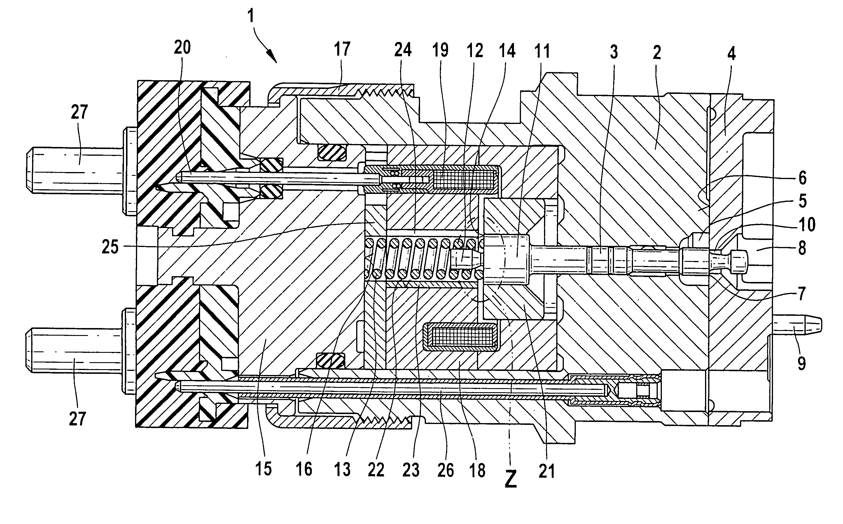
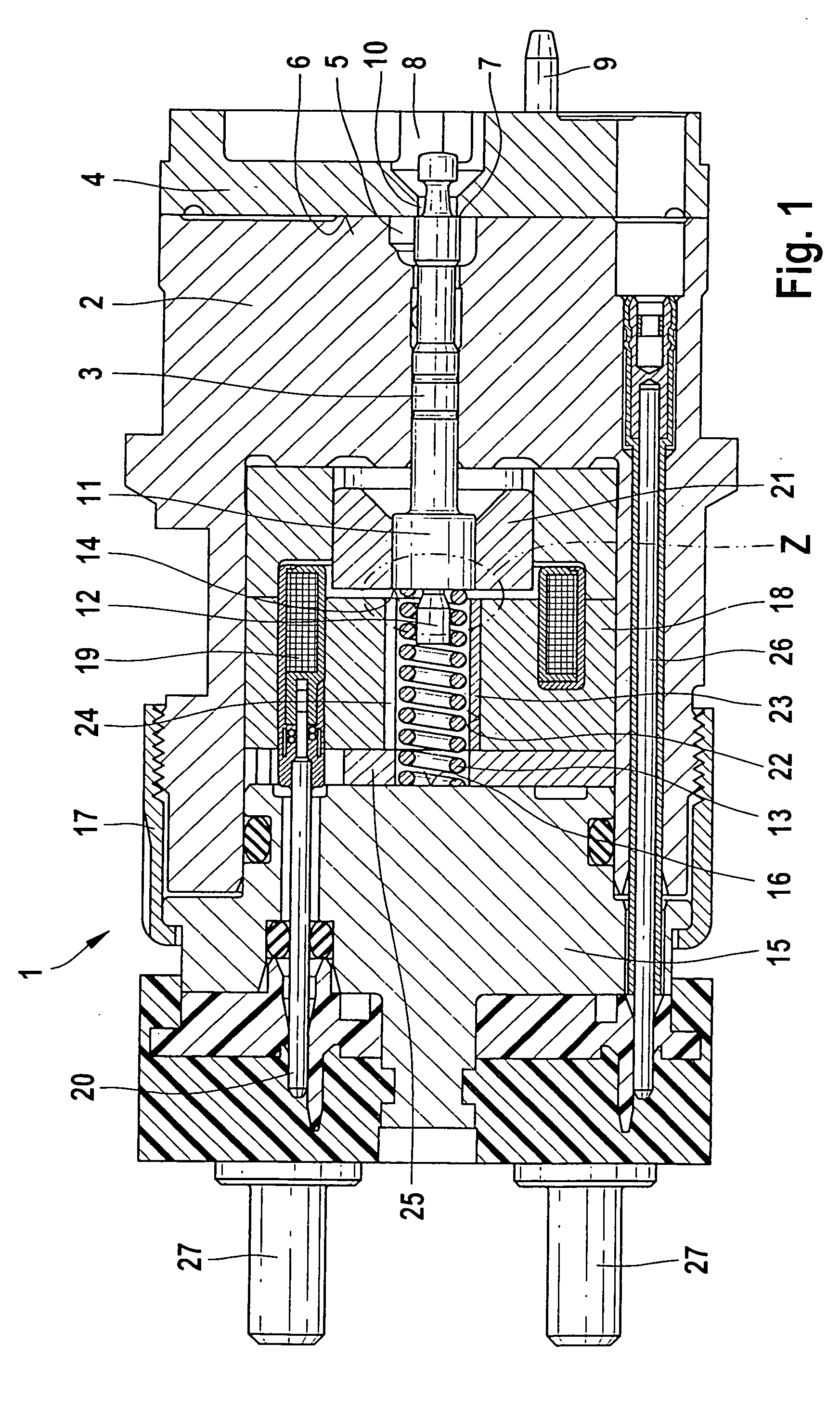
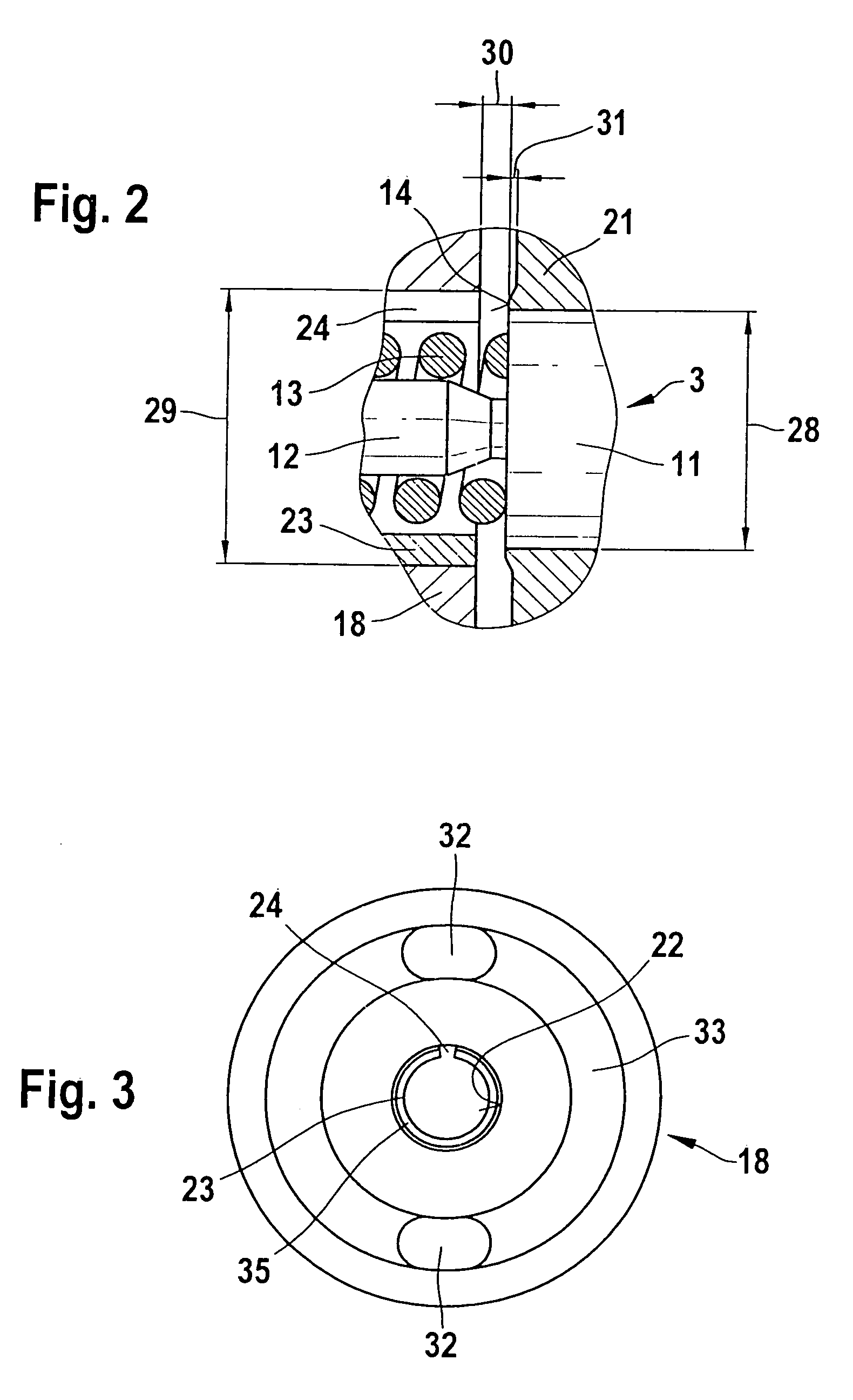
[0014] So that the valve needle will not strike the magnet cup when it opens, the outer diameter of the clamping sleeve is preferably greater than or equal to the diameter of the stop face of the valve needle. Because the width of the gaplike opening extending between the face ends makes up at most 25% of the sleeve circumference, kinking of the valve needle upon impact is avoided, and precise opening is thus achieved. An annular stop face and hence a uniform impact of the valve needle can be attained by providing that in the magnet cup, at least two clamping sleeves are received, whose gaplike openings extending between the face ends are located at different radial positions.

Problems solved by technology

A sleeve of magnetizable material has the disadvantage that even after the delivery of current to the coil ends, the magnetization is preserved, and the valve needle is thus initially kept in the open position by the clamping sleeve and does not close until after a delay.
Moreover, the material from which the clamping sleeve is made is preferably not deformable by the impact of the valve needle.
Lengthening of the needle stroke can for example lead to an increase in the injected fuel quantity and thus to increased fuel consumption.

Method used


Image

  • Fuel injector with clamping sleeve as a stop for a valve needle
  • Fuel injector with clamping sleeve as a stop for a valve needle
  • Fuel injector with clamping sleeve as a stop for a valve needle

Examples


Embodiment Construction

[0024]FIG. 1 shows a control valve 1 includes a valve body 2, with a bore received centrally in it, in which bore a valve needle 3 is guided. On the side toward an injection valve, not shown here, the valve body 2 is adjoined by a stop plate 4. On the side toward the stop plate 4, the bore in the valve body 2 opens up into a first valve chamber 5. The first valve chamber 5 is defined by an end face 6 of the stop plate 4. The first valve chamber 5 is adjoined by a bore 10 in the stop plate 4. The bore 10 opens into a second valve chamber 8. By means of the flat seat 7 on the valve needle 3, the bore 10 in the stop plate 4 can be opened or closed.

[0025] For the sake of installing the injection valve, not shown in FIG. 1, in the correct position on the control valve 1, a guide peg 9 is embodied on the stop plate 4. For assembly the guide peg 9 is introduced into a corresponding bore on the injection valve. In this way, it is assured that the bores for conduits passing through a plural...


PUM


Abstract

The invention relates to a fuel injector for internal combustion engines, having a control valve with an electromagnetically actuatable valve needle; a coil is received in a magnet cup made of magnetizable material. At least one clamping sleeve, with a gaplike opening extending between the face ends of the clamping sleeve, is received in the magnet cup. The invention also relates to a method for producing the fuel injector.

Description

CROSS-REFERENCE TO RELATED APPLICATIONS [0001] This application is based on German Patent Application 10 2004 028 523.3 filed Jun. 11, 2004, upon which priority is claimed. BACKGROUND OF THE INVENTION [0002] 1. Field of the Invention [0003] This invention relates to an improved fuel injector for internal combustion engines, and to a method of producing the fuel injector. [0004] 2. Description of the Prior Art [0005] For supplying fuel to internal combustion engines, fuel injection valves are often used at present. For meeting emissions limits and reducing fuel consumption, the fuel quantity injected into the individual cylinders must be dimensioned precisely. This requires extremely short opening and closing times of the injection valve. Moreover, the valve needle must have the same stroke each time it opens, to assure that the same quantity of fuel will be injected into the cylinder each time. This is attained by means of a stroke limitation. [0006] In the fuel injectors that are a...

Claims


Application Information

Patent Timeline
Patent Type & Authority Applications(United States)
IPC IPC(8): F02M63/00F02M59/46F02M51/06F02M51/00F02M61/16
CPCF02M51/005F02M61/161F02M61/168F02M63/0015F02M63/004F02M63/0043Y10S251/903
Inventor GRABANDT, PETER
Owner ROBERT BOSCH GMBH
Learn More