Shredding device for a shredding plant

a technology of shredding device and shredding plant, which is applied in the direction of grain treatment, etc., can solve the problems of compromising the quality of material separation, compromising the subsequent steps of separating materials, and uniform shredding action on scraps

Inactive Publication Date: 2011-07-14
DANIELI UK HLDG
View PDF11 Cites 4 Cited by
  • Summary
  • Abstract
  • Description
  • Claims
  • Application Information

AI Technical Summary

Benefits of technology

[0034]According to a fourth characteristic of the present invention, each of the protection elements has externally gripping and friction means, preferably conformed as trapezoid blocks which extend radially outwards. The gripping means allows the scrap, during the rotation of the drum, to be effectively accelerated radially outwards, towards the separation elements housed inside the shredder chamber, causing accelerated sizing of material to such a level that it can be quickly ejected from the machine.

Problems solved by technology

In this way, not all the parts of the scrap are subjected to an efficient shredding action, thus compromising the quality of separation of the materials, which is performed later.
The shredding action on the scrap is therefore not uniform, which compromises the subsequent steps of separating the materials.
Another disadvantage of known solutions is that the material, shredded or to be shredded, tends to accumulate inside the drum, and over time begins to wear away the components which comprise the drum.
This erosion of the internal drum components is particularly dangerous and reduces the life of the drum.
Continuous replacement of the component material is required, undertaken by welding at great cost.
The known solutions also have the disadvantage that the pins around which the hammers are rotatably connected, usually made of metal, tend to deform with use due to the force applied by the hammer.
In particular, it causes a deformation with humps at the sides of the hammer; over time and several hammer change cycles, this limits and impedes the replacement of the hammer shaft, making replacement of the hammers time consuming and expensive.
The typical solution exhibited by the state of the art would be to have a hydraulically actuated shaft removal means, exerting a massive force to shear the deformations off the damaged shaft, the risk being that the drum inside the machine can become misaligned within the housing of the drum.
Another disadvantage of known solutions is that the scrap tends to slide away, due to the rotation of the drum, while it is being shredded, along the protective shields, so that the case occurs where the scrap does not completely receive the expected blow from the hammer, since it has moved, returning back, for example, along the feed chute.

Method used


Image

  • Shredding device for a shredding plant
  • Shredding device for a shredding plant
  • Shredding device for a shredding plant

Examples


Embodiment Construction

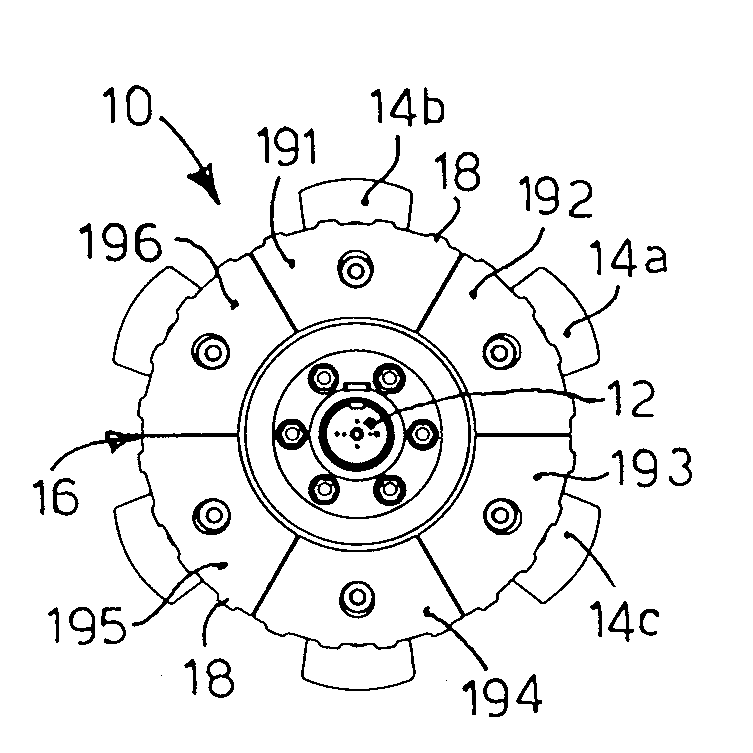
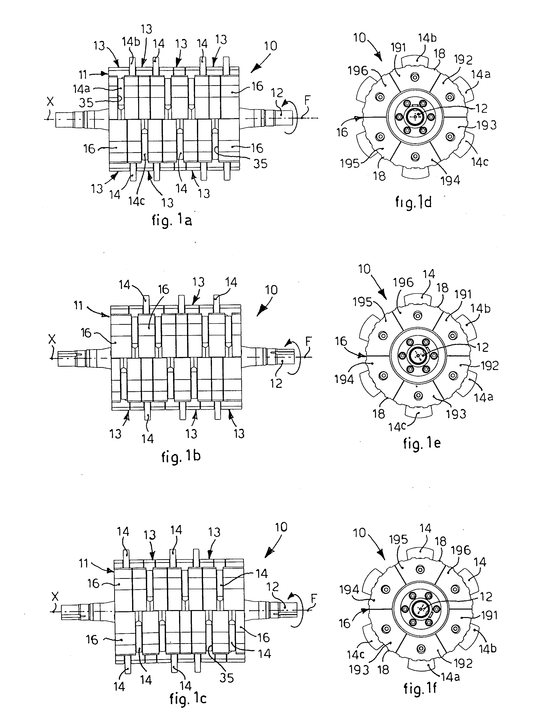
[0043]With reference to the attached drawings, a rotary shredding device 10 according to the present invention is able to be used inside a shredding chamber in a plant for shredding scrap, only partly visible in FIG. 5 and indicated by the reference number 50, with respect to which the scrap is fed through a feed pipe 38.

[0044]The device 10 comprises at least a rotary drum 11 of the modular type, consisting of a plurality of discoid elements, or modules 13, adjacent and kept together in a known manner, attached to a central hub 12.

[0045]The hub 12 is made to rotate, in a traditional manner, by drive means not shown in the drawings, around a longitudinal axis X for the rotatable movement of the drum 11 of the shredding device 10.

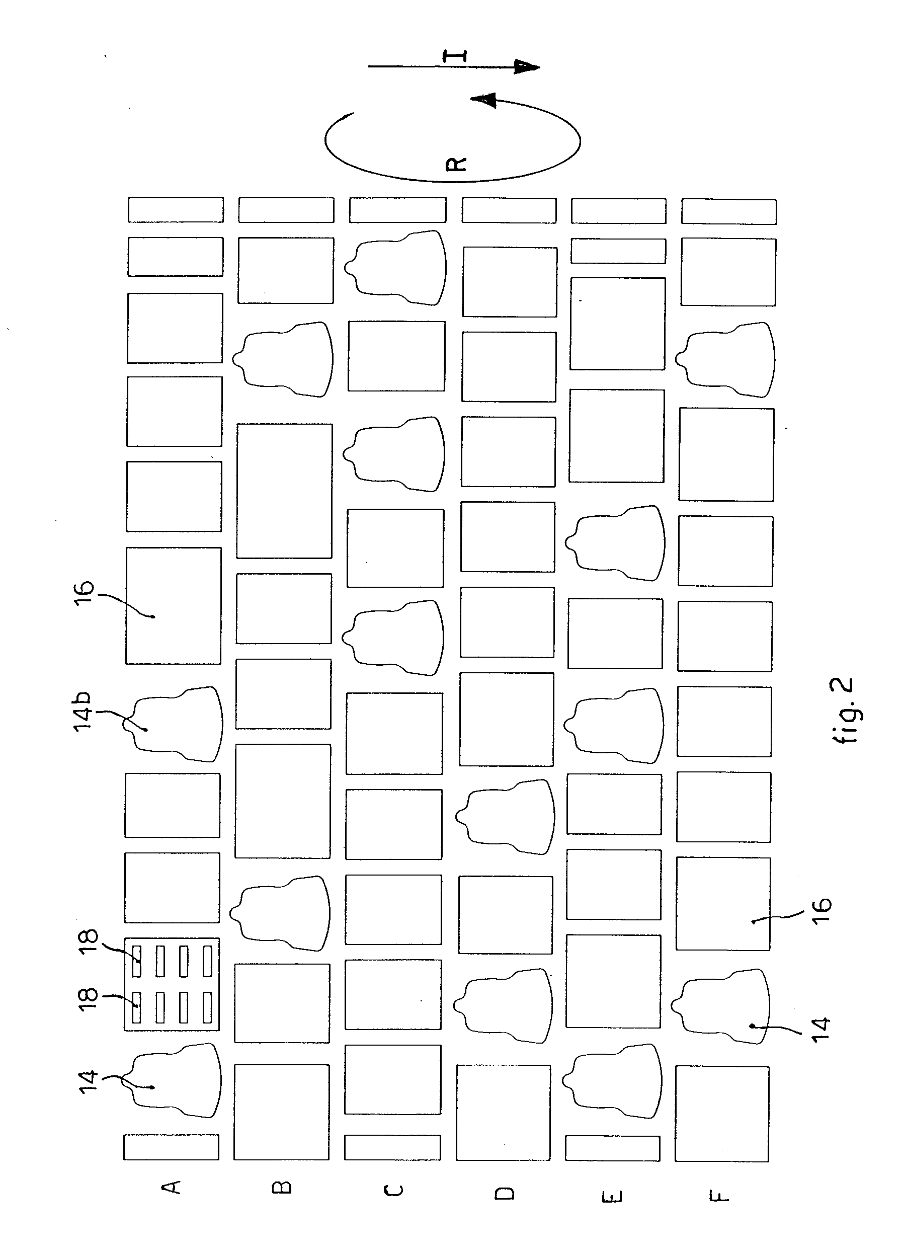
[0046]Along the lateral surface of the drum 11 a plurality of beating hammers 14 are pivoted peripherally, as will be described hereafter in more detail, which are conformed so as to effect the shredding action on the scrap fed inside the shredding device 10....


PUM


Abstract

A shredding device comprising a drum having a central hub rotating around an axis on which a plurality of discoid elements are mounted adjacent, able to rotate solidly together and carrying peripherally beating elements. Each discoid element comprises a set of beating elements which comprises at least a pair of beating elements and, along the axis, the pairs of beating elements of the discoid elements are disposed angularly staggered with respect to the same axis.

Description

FIELD OF THE INVENTION[0001]The present invention concerns a rotary shredding device that can be used in a plant for shredding, advantageously but not in limiting way of scrap, such as for example vehicles, trailers or other, in which the scrap is loaded whole and / or shredded so as to reduce the bulk and to sub-divide the different materials of which the scrap is made up, for example metal, glass, plastic or other. In particular, the rotary shredding device according to the present invention comprises at least a rotary drum along whose lateral surface a plurality of beating elements are peripherally pivoted, which are conformed so as to carry out the action of shredding the scrap.BACKGROUND OF THE INVENTION[0002]Plants for shredding scrap are known, such as for example vehicles, trailers or other, in which the scrap is loaded substantially whole and is shredded, both to reduce the bulk and also to separate efficiently the materials that make it up.[0003]Known plants for shredding sc...

Claims


Application Information

Patent Timeline
Patent Type & Authority Applications(United States)
IPC IPC(8): B02C13/28
CPCB02C13/04B02C2013/2808B02C13/28
Inventor LESTER, JOHNROSE, CRAIG
Owner DANIELI UK HLDG
Why Eureka
Try Eureka