Excavator for underground excavating, rotary excavator and underground excavating method
An excavating device, a technology of a rotating body, applied to drilling equipment and methods, driving devices for drilling in boreholes, earthwork drilling and mining, etc.
- Summary
- Abstract
- Description
- Claims
- Application Information
AI Technical Summary
Problems solved by technology
Method used
Image
Examples
no. 1 approach
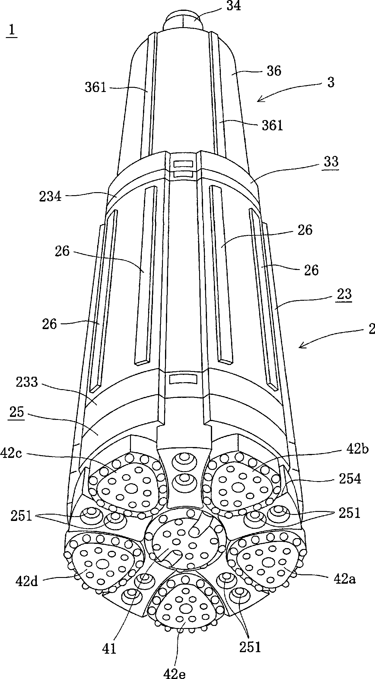
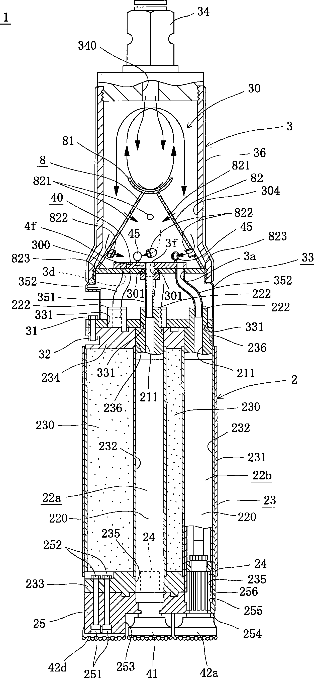
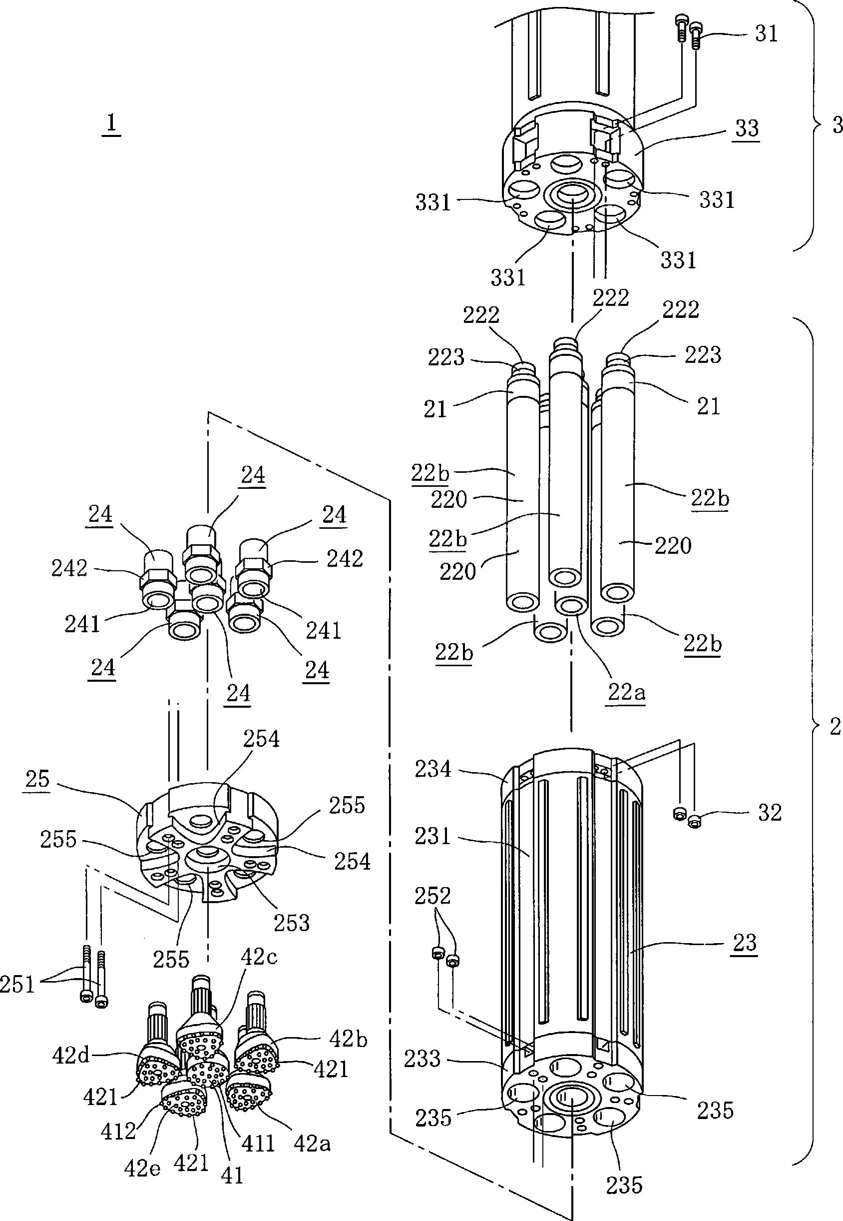
[0074] Figure 1 to Figure 9 It is a figure for demonstrating the 1st Embodiment of the excavation apparatus for underground excavations of this invention.
[0075] figure 1 It is a perspective explanatory view of the excavating device of the first embodiment viewed from the tip side; figure 2 for figure 1 An explanatory diagram of a longitudinal section of the excavating device shown; image 3 for figure 1 The illustrated exploded perspective explanatory view of the excavating device shows a disassembled state of the air tank part and the excavating bit part removed from the gas tank part. and, in image 3 In , illustration of the base side (upper side) of the air tank member 3 is omitted.
[0076] Figure 4 It is an explanatory side view showing the internal structure of the piston box part housed in the excavation bit part in a longitudinal section, by Figure 4 (a) to (d) show the state of the built-in piston moving up and down (forward and backward motion) in chr...
no. 2 approach
[0175] Figure 11 with Figure 12 The second embodiment of the excavating apparatus for underground excavation according to the present invention will be described.
[0176] Figure 11 It is an explanatory view of a longitudinal section of an excavating device according to a second embodiment, Figure 12 for Figure 11 The horizontal section of the gas guiding component shown is an explanatory top view showing the internal structure of the rotating body, which is the same as that described in Example 1. Figure 7 corresponding figure.
[0177] In addition, the same or equivalent parts as those of the first embodiment are denoted by the same symbols. In addition, descriptions of parts described in the first embodiment will be omitted, and differences will be mainly described.
[0178] In the above-mentioned first embodiment (refer to figure 2 with Figure 7 ), through the rotating body 40 to control the opening of the five peripheral separation holes 3a, 3b, 3c, 3d, 3e...
no. 3 approach
[0207] Figure 14 to Figure 16 A third embodiment of the excavation apparatus for underground excavation according to the present invention will be described.
[0208] Figure 14 It is an explanatory view of a longitudinal section of an excavating machine according to a third embodiment. Figure 15 (a) for and Figure 4 The same longitudinal sectional explanatory drawing shown in (a), Figure 15 (b) is a vertical cross-sectional explanatory view of another piston box member housed in the digging bit unit. Figure 16 for Figure 14 It is a perspective explanatory view of the fluid guide member disposed in the air tank unit of the excavator shown.
[0209] Next, the excavating device 1b will be described. In addition, the same or equivalent parts as those of the first and second embodiments are denoted by the same symbols. In addition, description of parts described in the first and second embodiments will be omitted, and differences will be mainly described.
[0210] (e...
PUM
| Property | Measurement | Unit |
|---|---|---|
| Diameter | aaaaa | aaaaa |
Abstract
Description
Claims
Application Information
 - R&D
- Intellectual Property
- Life Sciences
- Materials
- Tech Scout
- Unparalleled Data Quality
- Higher Quality Content
- 60% Fewer Hallucinations
Browse by: Latest US Patents, China's latest patents, Technical Efficacy Thesaurus, Application Domain, Technology Topic, Popular Technical Reports.
© 2025 PatSnap. All rights reserved.Legal|Privacy policy|Modern Slavery Act Transparency Statement|Sitemap|About US| Contact US: help@patsnap.com


