Encoder scale error compensation employing comparison among multiple detectors

a technology of multiple detectors and encoders, applied in the field of position encoders, can solve the problems of affecting the accuracy of phase measurement performed by the encoder, the scale itself is ultimately limited by the perfection of the scale, and the encoder cannot capture errors that depend on the operating environment, etc., to achieve the effect of low cost and higher resolution

Inactive Publication Date: 2005-12-15
THE GSI GRP LLC
View PDF7 Cites 63 Cited by
  • Summary
  • Abstract
  • Description
  • Claims
  • Application Information

AI Technical Summary

Benefits of technology

[0011] In a first embodiment, the calculating and use of compensation values is done on the fly during normal encoder operation, providing for simplicity and low cost. Generally, an encoder of this first type is best suited for applications having relatively low resolution requirements. In embodiments of a second type, the compe...

Problems solved by technology

It is well known in the art that the accuracy of a scale-based optical encoder is ultimately limited by the perfection of the scale itself.
In diffractive optical encoders, various scale errors affect the position, period, straightness, and intensity profile of the interference fringes, which in turn affect the accuracy of the phase measurement performed by the encoder.
Although the above compensation technique can be quite accurate, it has the drawback that the calibration is performed outside the system in which the encoder is used, and thus necessarily cannot capture errors that depend on the operating environment, such as temperature-related scale errors.
Also, it is cumbersome or practically impossible to perform any re-calibration of the encoder once it is installed in an operating system, because of the need to connect it to a separate me...

Method used


Image

  • Encoder scale error compensation employing comparison among multiple detectors
  • Encoder scale error compensation employing comparison among multiple detectors
  • Encoder scale error compensation employing comparison among multiple detectors

Examples


Embodiment Construction

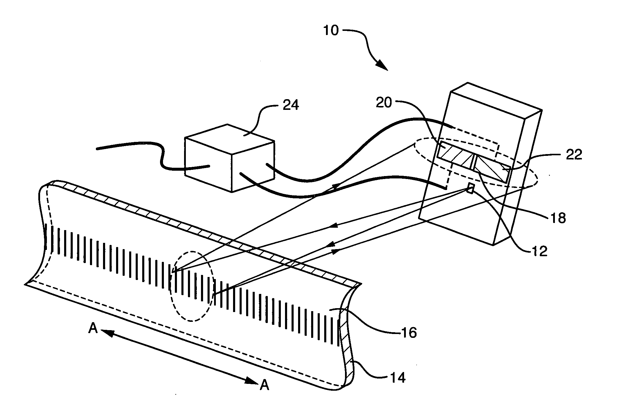
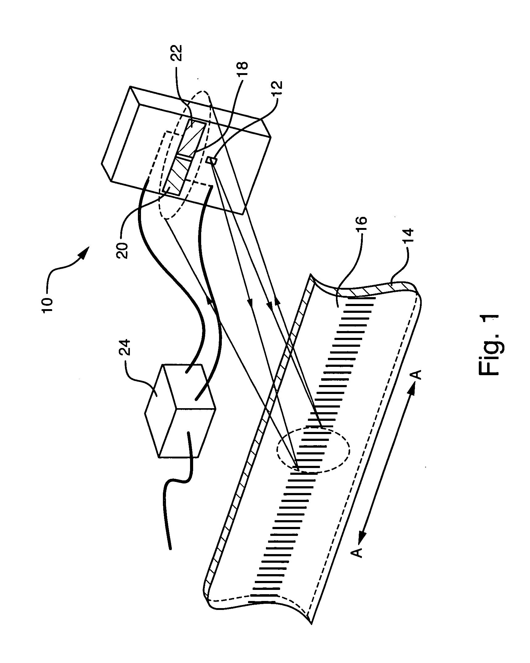
[0025] In FIG. 1, sensor apparatus 10 is installed as part of a reflective, diffractive optical encoder. A source 12 illuminates a scale 14 on which a periodic, reflective diffraction grating 16 has been created. Light from the source 12 is reflectively diffracted from the scale 14 toward the sensor apparatus 10, which in the illustrated embodiment includes an optical detector 18. The diffraction grating 16 generates multiple orders of diffracted light which interfere with each other to form an optical fringe pattern (not illustrated) on the detector 18.

[0026] The fringe pattern is ideally a sinusoid characterized by a period P. Conceptually, when the scale 14 moves laterally relative to the detector 18 along the direction indicated by double headed arrow A-A, the fringe pattern moves a proportional distance on the face of detector 18. An accurate measurement of the changes in the phase of the fringe pattern is a proportional measurement of the movement of the scale 14. As discusse...


PUM


Abstract

An encoder calculates position error values and applies compensation values to encoder position measurements in-situ. The encoder includes a scale and a multi-section detector for detecting a spatially periodic pattern, such as an optical interference pattern, produced by the scale. The detector includes spatially separated first and second sections. A signal processor estimates respective phase values from detector sections and calculates a phase difference reflecting a spatial position error in the scale. A compensation value is calculated from the phase difference and included in the estimate of the scale position to compensate for this spatial position error. The compensation values may be calculated and used on the fly, or calculated and saved during an in-situ calibration operation and then utilized during normal operation to compensate uncorrected measurements.

Description

BACKGROUND OF THE INVENTION [0001] The present invention is related to the field of position encoders including diffractive optical position encoders. [0002] It is well known in the art that the accuracy of a scale-based optical encoder is ultimately limited by the perfection of the scale itself. In diffractive optical encoders, various scale errors affect the position, period, straightness, and intensity profile of the interference fringes, which in turn affect the accuracy of the phase measurement performed by the encoder. [0003] A typical approach for reducing the significance of scale errors is to perform a calibration measurement of the scale, either at the factory or in the field, and to apply the calibration to subsequent operational measurements. Usually the scale position is measured relative to an encoder sensor head while being translated on a stage whose position is independently sampled with a second, known good position measuring system (the “reference” system), such a...

Claims


Application Information

Patent Timeline
IPC IPC(8): G01D5/34G01D5/36G01D5/38
CPCG01D5/36G01D5/38
Inventor GOLDMAN, ANDREWTHORBURN, WILLIAM G.
Owner THE GSI GRP LLC
Why Eureka
Try Eureka