
Belt over compliant roller used with molding roller

a technology of compliant rollers and molding rollers, applied in the field of thermoplastic film manufacturing methods, can solve the problems of insufficient precision of the manufacturing process for producing glossy or matte finishes on photographic paper for the purpose of manufacturing light redirecting films, the manufacturing process used to manufacture other patterned films may not adequately reproduce optical elements, etc., to achieve accurate replication of specific optical elements, increase the efficiency of liquid crystal displays, and increase the effect of efficiency

Inactive Publication Date: 2005-12-15
ROHM & HAAS DENMARK FINANCE
View PDF14 Cites 7 Cited by
  • Summary
  • Abstract
  • Description
  • Claims
  • Application Information

AI Technical Summary

Benefits of technology

[0010] In accordance with example embodiments of the present invention, the manufacturing process is able to produce light redirecting films that can be used in a variety of applications. For example, by using the manufacturing process in accordance with example embodiments of the invention, the light redirecting film can be produced with an accurate replication of specific optical elements. This replication of the specific optical elements allows for a film that can create a substantial increase in efficiency of a liquid crystal display. Accordingly, this increase in efficiency can extend the battery life of a mobile device (e.g. a cellular phone, laptop computer, digital camera, etc.) A manufacturing process of example embodiments will allow for a thin film to be produced with discreet optical elements, having a uniform thickness. A light redirecting film without the discreet optical elements and uniform thickness may not be effective in increasing the efficiency of a display device.

Problems solved by technology

As tolerances of a manufacturing process become higher, the manufacturing process generally becomes more complicated and expensive.
Accordingly, the precision of the manufacturing process for producing glossy or matte finishes on photographic paper may be inadequate for purposes of manufacturing light redirecting films.
For example, the manufacturing process used to manufacture other patterned films may not adequately reproduce optical elements of a light redirecting film or provide a uniform thickness of the film, which may be required for a light redirecting film to be usable.

Method used


Image

  • Belt over compliant roller used with molding roller
  • Belt over compliant roller used with molding roller
  • Belt over compliant roller used with molding roller

Examples


Embodiment Construction

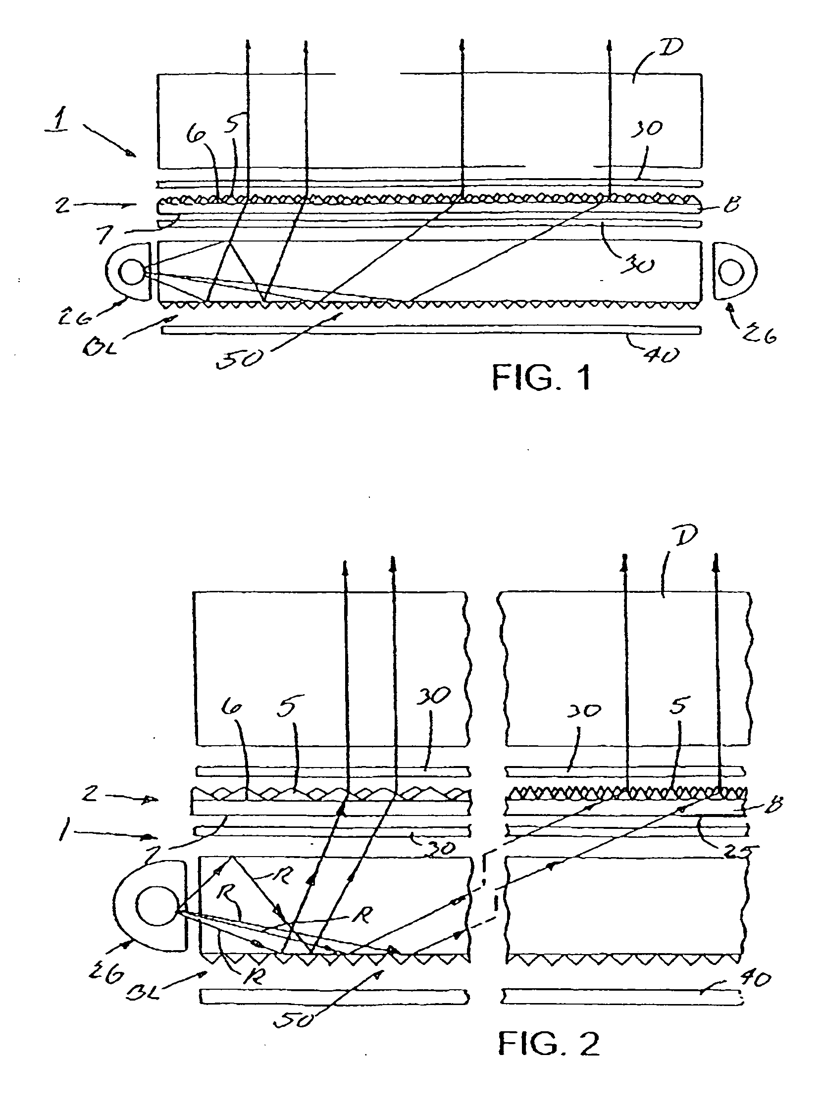
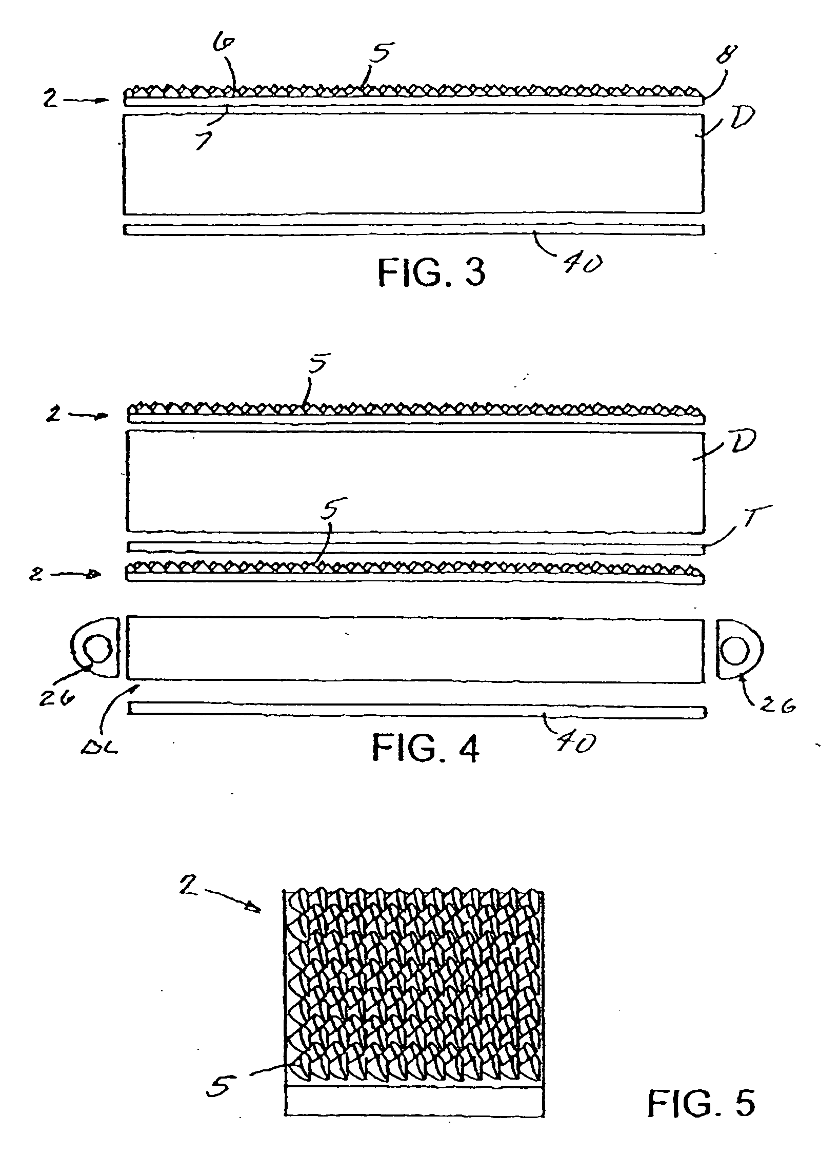
[0022] Example FIGS. 1 and 2 schematically show one form of light redirecting film system 1 in accordance with example embodiments of the present invention. Light redirecting film system 1 may include a light redirecting film 2 that redistributes more of the light emitted by a backlight BL (or other light source) toward a direction more normal to the surface of the film. Film 2 may be used to redistribute light within a desired viewing angle from almost any light source for lighting. For example, film 2 may be used with a display D (e.g. in a liquid crystal display, used in laptop computers, word processors, avionic displays, cell phones, and PDAs) to make the displays brighter. A liquid crystal display can be any type, including a transmissive liquid crystal display as schematically shown in example FIGS. 1 and 2, a reflective liquid crystal display as schematically shown in example FIG. 3, or a transflective liquid crystal display as schematically shown in example FIG. 4.

[0023] T...


PUM

PropertyMeasurementUnit
glass transition temperatureaaaaaaaaaa
dwell timeaaaaaaaaaa

Abstract

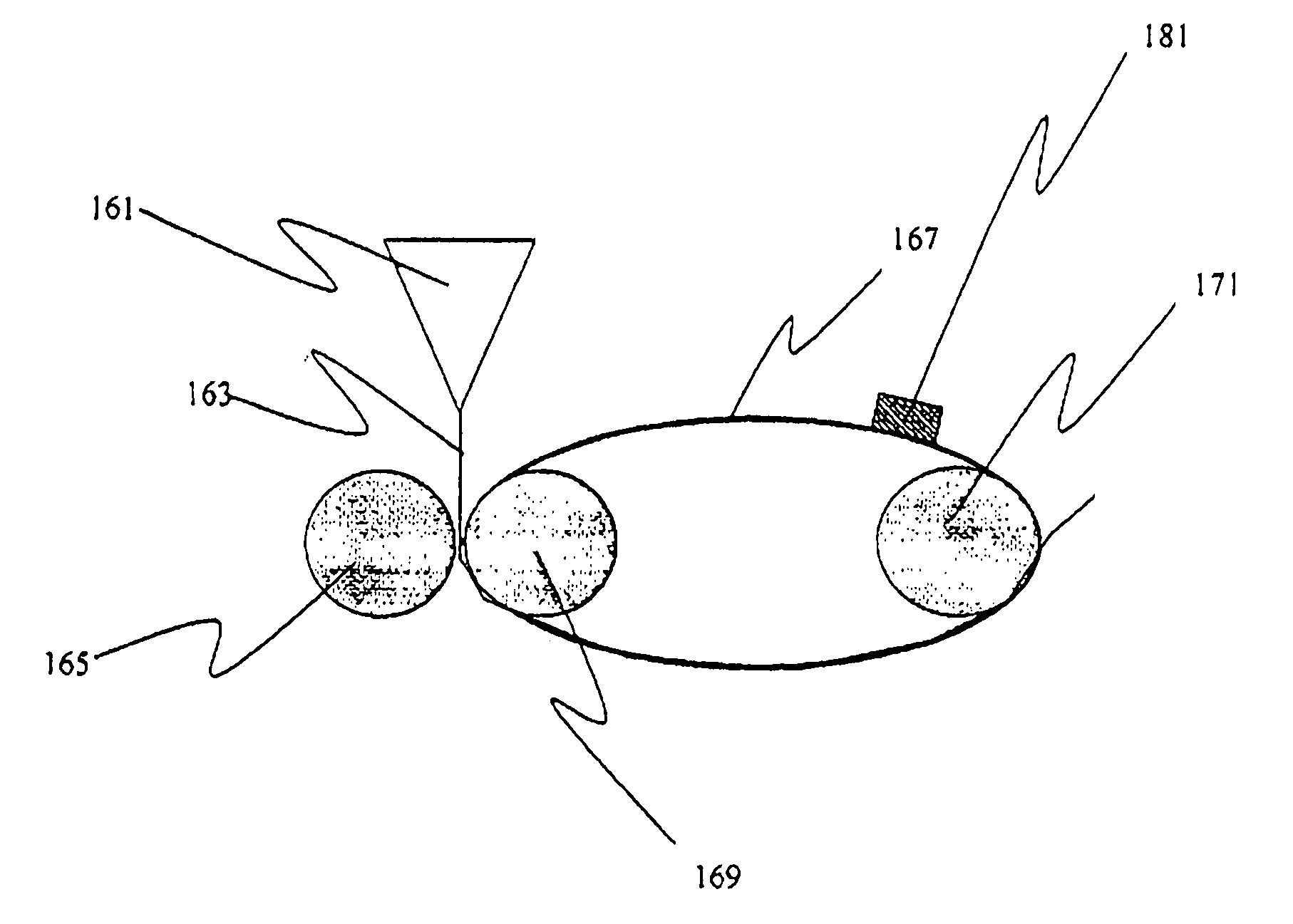
The invention relates to an apparatus and method of making a solid film. Viscous material (163) is input into a nip between a patterned roller (165) and a belt (167). The nip between the patterned roller (165) and belt (167) is facilitated by a compliant roller (169). Accordingly, a film may be produced that has discrete optical elements and a smooth backside.

Description

CROSS REFERENCE TO RELATED APPLICATIONS [0001] The present application is related to U.S. patent application Ser. No. ______ (Kodak Ref. No. 87521 / PAL), which is incorporated by reference in entirety.FIELD OF THE INVENTION [0002] Example embodiments of the present invention relate to a method of manufacturing a thermoplastic film having optical elements on one side of the film and a smooth surface on another side of the film. BACKGROUND OF THE INVENTION [0003] Films with patterned surfaces are made for a variety of applications. For example, photographic paper may include a film with a matte or glossy finish. This matte finish or glossy finish may produce a desirable effect on a photograph when viewed by a casual observer. A glossy or matte finish requires a photographic paper manufacturing process with certain tolerances (i.e. a certain level of precision). As tolerances of a manufacturing process become higher, the manufacturing process generally becomes more complicated and expen...

Claims


Application Information

Patent Timeline
Patent Type & Authority Applications(United States)
IPC IPC(8): B29C43/22B29C59/02B29C59/04B29D11/00
CPCB29C59/022B29C59/04B29L2011/00B29C2043/486
Inventor BOURDELAIS, ROBERT P.BRICKEY, CHERYL J.BENSON, JOHN E.
Owner ROHM & HAAS DENMARK FINANCE
Learn More