Differential flux permanent magnet machine

Inactive Publication Date: 2005-12-15
TETMEYER MICHAEL EDWARD
View PDF24 Cites 7 Cited by
  • Summary
  • Abstract
  • Description
  • Claims
  • Application Information

AI Technical Summary

Benefits of technology

[0007] Accordingly, it is an aspect of the present invention to provide a relatively inexpensive motor which

Problems solved by technology

However, unless a motor controller is connected to such an induction motor, precise speed regulation is not possible when the motor is subjected to loading.
However, a motor controller must often be used with these

Method used


Image

  • Differential flux permanent magnet machine
  • Differential flux permanent magnet machine
  • Differential flux permanent magnet machine

Examples


Embodiment Construction

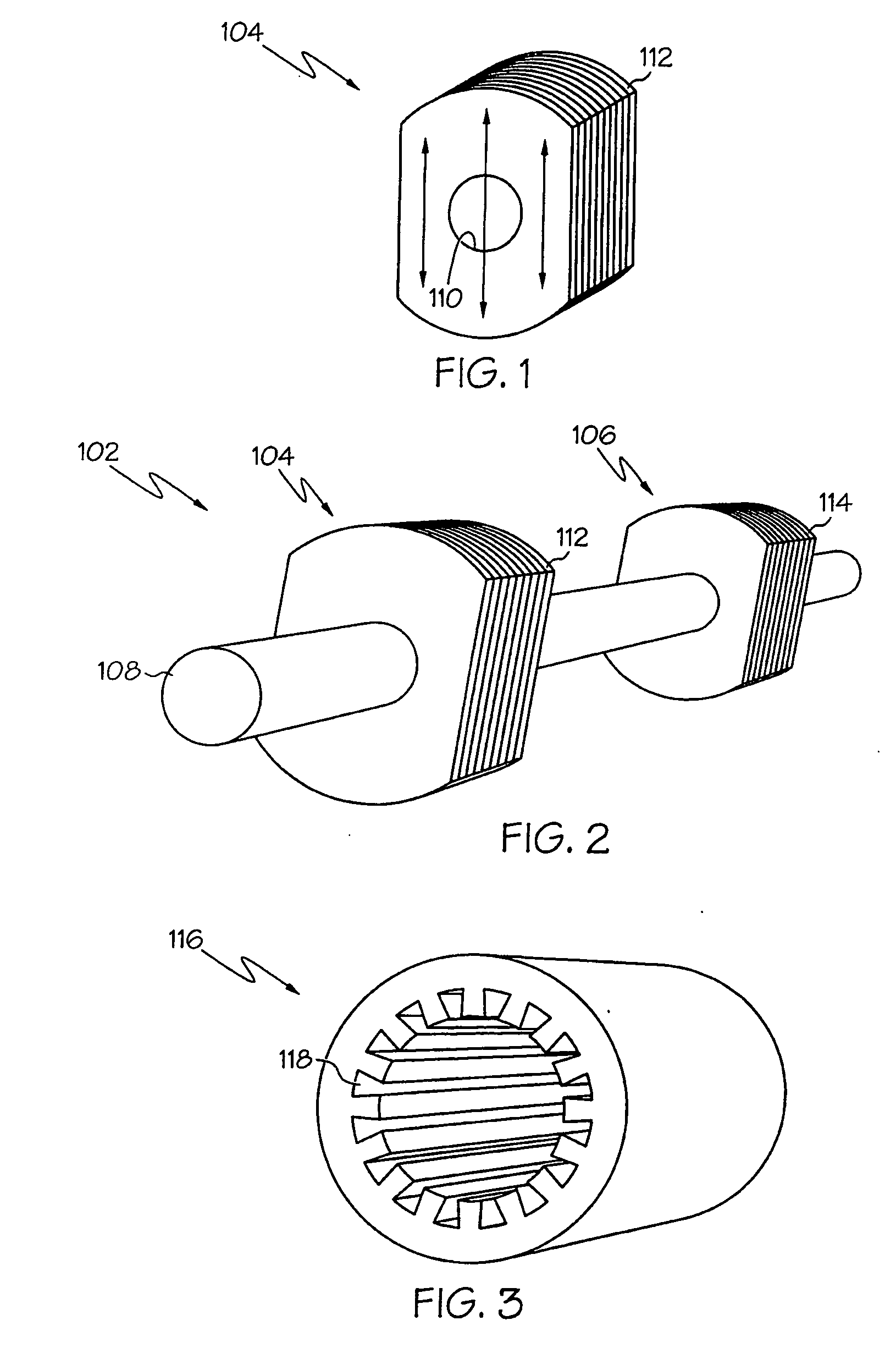
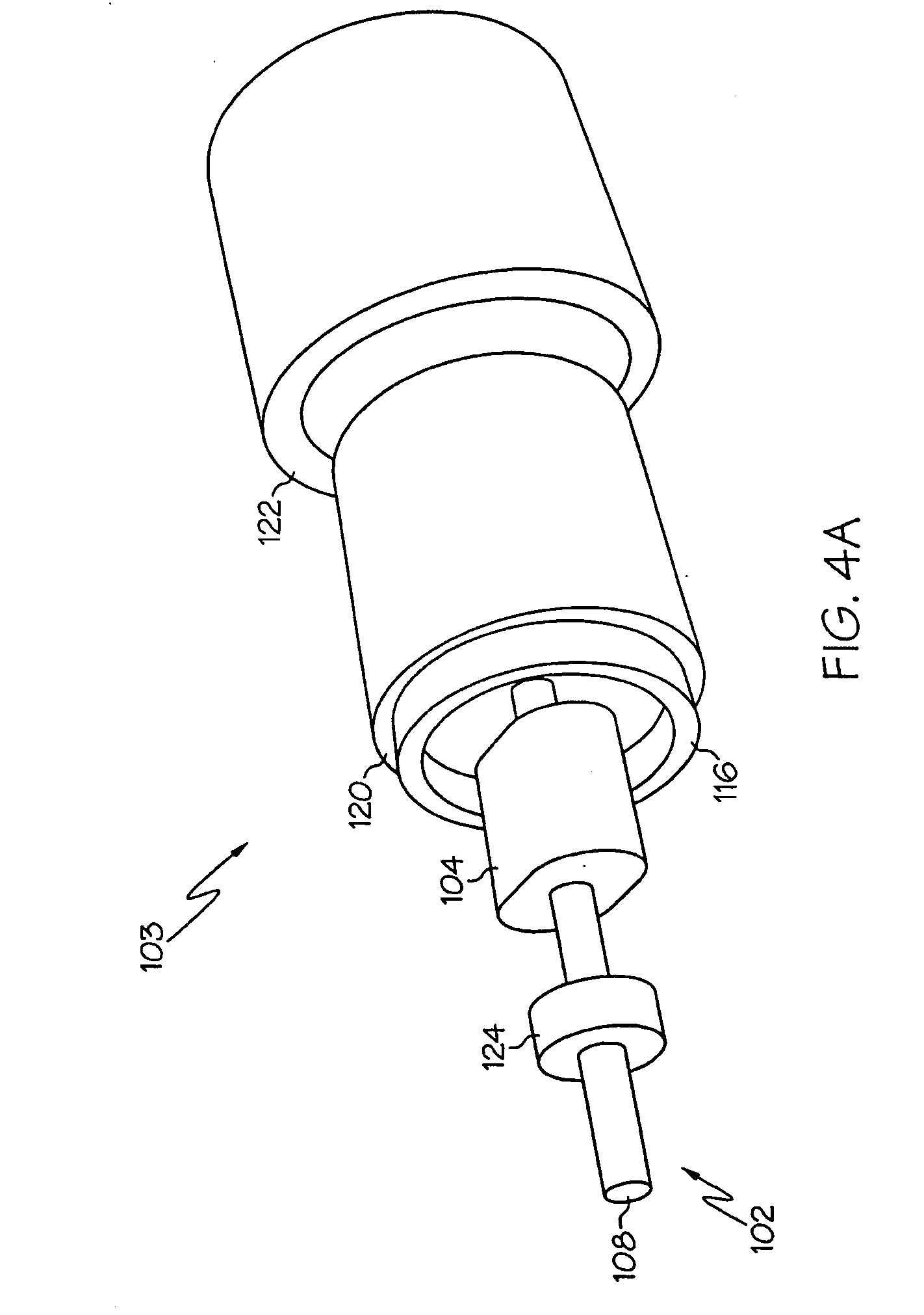
[0053] An embodiment of the invention and its operation is hereinafter described in detail in connection with the views and examples of FIGS. 1-92, wherein like numbers indicate the same or corresponding elements throughout the views. One differential flux motor in accordance with the teachings of the present invention is depicted in FIG. 5C as a motor assembly 100. The motor assembly 100 is shown in FIG. 5C to include a rotor 102 and a stator assembly 103. The rotor 102 includes a shaft 108 to which a pulley, gear, fan, or other driven device may be attached. The shaft 108 may be formed of a ferromagnetic material such as steel. The stator assembly 103 comprises a shell 136. The shell 136 can be cylindrical and can be formed from ferromagnetic material (e.g., a single piece of rolled steel). End plates 138, 140 can be provided and can be constructed of non-ferromagnetic material (e.g., aluminum) and can contain bearing seats and provisions (e.g., apertures 146, 148 shown in FIG. 5C...


PUM


Abstract

A differential flux motor includes a rotor and a stator assembly. The rotor has a shaft and rotor section(s) attached to the shaft. The stator assembly has first and second stator cores, first and second magnets, and a shell. The first stator core includes a first winding and concentrically surrounds at least a portion of the rotor. The second stator core has a second winding and concentrically surrounds at least a different portion of the rotor. The first magnet concentrically surrounds at least part of the first stator core, and the second magnet concentrically surrounds at least part of the second stator core. The first and second magnets are formed from permanent magnet material and have opposite polarities. The shell concentrically surrounds at least part of each of the first magnet and the second magnet. A method of manufacturing a differential flux motor is also provided.

Description

RELATED APPLICATION [0001] The present application claims priority of U.S. Provisional Application Ser. No. 60 / 578,215 filed Jun. 9, 2004 and hereby incorporates the same Provisional Application by reference.TECHNICAL FIELD [0002] The present invention relates to motors, particularly motors having a stator assembly including permanent magnets. BACKGROUND OF THE INVENTION [0003] Many types of electric motors are available in the marketplace, all of which have certain advantages and disadvantages for particular applications. For example, a standard induction type motor is inexpensive, low-maintenance, and can be started without use of a motor controller (e.g., a variable frequency drive). However, unless a motor controller is connected to such an induction motor, precise speed regulation is not possible when the motor is subjected to loading. [0004] Alternatively, an alternating current synchronous type motor can maintain precise speed regulation, even under loading. However, a motor ...

Claims


Application Information

Patent Timeline
IPC IPC(8): H02K37/00H02K21/44H02K17/00H02K19/10
CPCH02K19/103H02K21/44H02K2201/12
Inventor TETMEYER, MICHAEL EDWARD
Owner TETMEYER MICHAEL EDWARD
Why Eureka
Try Eureka