Signal generator circuit and level shifter with signal generator circuit

a signal generator and signal generator technology, applied in the field of level shifters, can solve the problems of immense amount of power consumed for nothing

Inactive Publication Date: 2005-12-15
LAPIS SEMICON CO LTD
View PDF14 Cites 7 Cited by
  • Summary
  • Abstract
  • Description
  • Claims
  • Application Information

AI Technical Summary

Benefits of technology

[0040] It is an object of the present invention to provide a signal generator circuit which prevents a timing at which an output signal at high voltage level changes from shifting from a timing at which an output signal at low voltage level changes such that no through current flows between a high voltage power supply Vpp and a ground potential VSSH of a level shifter with the signal generator circuit (particularly, a signal generator circuit which shifts a timing to generate a low voltage control signal for controlling the level shifter from a timing at which a high voltage control signal for controlling the level shifter is generated, such that a timing at which the output signal transitions to “H” is advanced, and a timing at which the output signal transitions to “L” is delayed).
[0041] It is another object of the present invention to provide a level shifter having a signal generator circuit which eliminates a through current by using the foregoing signal generator circuit.
[0042] To solve the aforementioned problem, a signal generator circuit according to a first aspect of the present invention has an output adjustor circuit for outputting a first output signal and a second output signal in accordance with an input signal, and a level shifter unit for converting a voltage level in accordance with the input signal to output a third output signal and a fourth output signal, wherein in response to a rising of the input signal, the first output signal first changes, the third and fourth output signals next change, and then the second output signal changes, and in response to a falling of the input signal, the second output signal first changes, the third and fourth output signals change, and then the first output signal changes. The signal generator circuit according to the first aspect of the present invention can operate subsequent circuits with stability because the timing at which the output signal at high voltage level changes does not shift from the timing at which the input signal at low voltage signal changes.
[0043] Also, a level shifter having a signal generator circuit according to a second aspect of the present invention has the signal generator circuit according to the first aspect of the present invention, and is characterized by outputting a first and a second amplified output signal which have amplified voltage levels, and simultaneously transition to “H” level or “L” level based on one of the first and second output signals and one of the third and fourth output signals of the signal generator circuit. The level shifter having a signal generator circuit according to the second aspect of the present invention can prevent a through current from occurring between the high voltage power supply and the ground potential the timing at which the output signal at high voltage level changes does not shift from the timing at which the input signal at low voltage level changes.
[0044] According to the present invention, a signal generator circuit can be provided for eliminating a shift of a timing at which an output signal at high voltage level changes from a timing at which an input signal at low voltage level changes.
[0045] Further, by incorporating the signal generator circuit according to the present invention, a level shifter can be provided for eliminating a through current.

Problems solved by technology

This causes a problem that the through currents break a variety of circuits incorporated in the apparatus.
Another problem lies in that an immense amount of power is consumed for nothing.
In addition, since the through current is a useless current, an immense amount of power is consumed for nothing.

Method used


Image

  • Signal generator circuit and level shifter with signal generator circuit
  • Signal generator circuit and level shifter with signal generator circuit
  • Signal generator circuit and level shifter with signal generator circuit

Examples


second embodiment

[Second Embodiment]

(Configuration of Signal Generator Circuit)

[0120] Since the signal generator circuit 6 according to the first embodiment employs the delay elements DLY11-DLY12, DLY21-DLY21, it is necessary to adjust operating speeds of the delay elements DLY11-DLY12, DLY21-DLY21 and the level shifter unit, but the adjustment is difficult. To eliminate this difficulty, a second embodiment provides a signal generator circuit which does not employ the delay elements DLY11-DLY12, DLY21-DLY21.

[0121] The following description will be made on the specific configuration of a signal generator circuit 7 according to the second embodiment of the present invention. FIG. 15 is a diagram showing the configuration of the signal generator circuit according to the second embodiment.

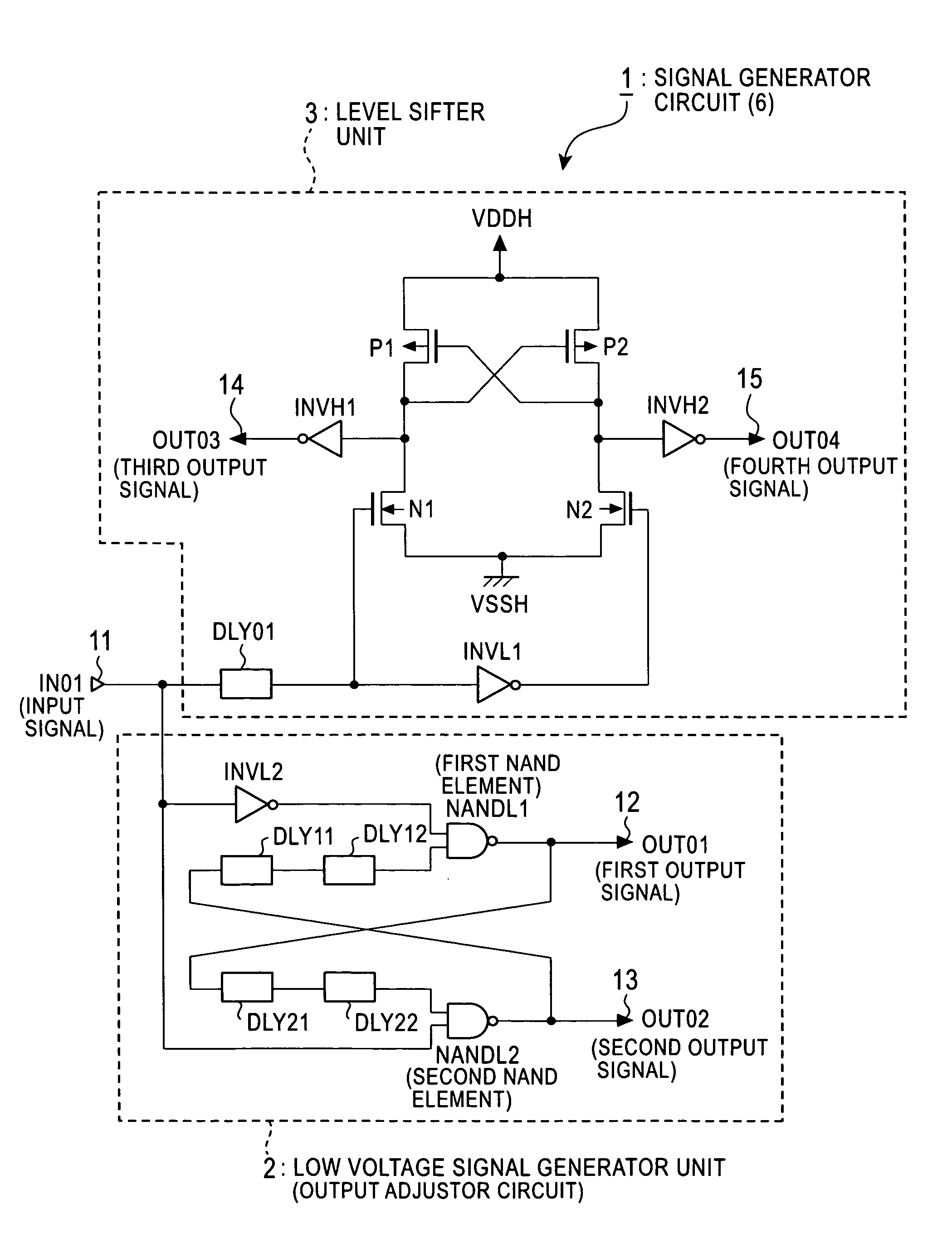
[0122] As shown in FIG. 15, the signal generator circuit 7 comprises an input terminal 11 for receiving an input signal IN01; an output terminal 12 for outputting a first output signal OUT01; an output terminal 13 ...


PUM


Abstract

A signal generator circuit prevents a shift of a timing at which an output signal at high voltage level changes from a timing at which an output signal at low voltage level changes, and a level shifter prevents a through current from flowing between a high voltage power supply and a ground potential. The signal generator circuit has an output adjustor circuit for outputting a first output signal and a second output signal in accordance with an input signal, and a level shifter for converting a voltage level in accordance with the input signal to generate a third output signal and a fourth output signal. In response to a rising of the input signal, the first output signal first changes, then the third and fourth output signals change, and subsequently the first output signal changes.

Description

BACKGROUND OF THE INVENTION [0001] 1. Field of the Invention [0002] The present invention relates to a level shifter for simultaneously generating complementary outputs at “H” level or “L” level, and a signal generator circuit suitable for controlling the level shifter. [0003] 2. Description of the Related Art [0004] Conventionally, there have existed several level shifters for simultaneously generating complementary outputs at “H” level or “L” level, for example, a first level shifter 10 shown in FIG. 1, a second level shifter 20 shown in FIG. 2, and the like. These level shifters are combined with a signal generator circuit 5 shown in FIG. 3, and receive part of signals outputted from the signal generator circuit 5 as control signals. [0005] In the following, the signal generator circuit 5 will be first described with reference to FIGS. 3 and 4, the first level shifter 10 and second level shifter 20 will be next described with reference to FIGS. 1 and 2, and a first level shifter ...

Claims


Application Information

Patent Timeline
Patent Type & Authority Applications(United States)
IPC IPC(8): H03K3/356H03B1/00H03K19/0185H03K17/16H03K3/037
CPCH03K3/037H03K3/356113
Inventor HONDA, TAKASHI
Owner LAPIS SEMICON CO LTD
Why Eureka
Try Eureka