Printing apparatus and printing method

a printing apparatus and printing method technology, applied in printing, inking apparatus, power drive mechanisms, etc., can solve the problems of high manufacturing cost, fraction defective, manufacturing cost rise, etc., and achieve the effect of low cost and high quality printing

Inactive Publication Date: 2005-12-15
CANON KK
View PDF3 Cites 28 Cited by
  • Summary
  • Abstract
  • Description
  • Claims
  • Application Information

AI Technical Summary

Benefits of technology

[0030] Further, a printing apparatus using a full-line print...

Problems solved by technology

It is, however, difficult to faultlessly machine and manufacture all ink discharge nozzles (to be referred to as nozzles hereinafter) and printing elements arrayed along the entire width of the printing area in the line printer using the full-line printhead.
It is hard for the manufacturing process to faultlessly machine and manufacture such a large number of nozzles and corresponding printing elements.
Even if a printhead can be manufactured faultlessly, the fraction defective and manufacturing cost rise.
However, the conventional “connecting head” readily ...

Method used


Image

  • Printing apparatus and printing method
  • Printing apparatus and printing method
  • Printing apparatus and printing method

Examples


first embodiment

[0114]FIG. 11 is a view showing the nozzle layout of a full-line printhead according to the first embodiment of the present invention.

[0115] Referring to FIG. 11, 19 nozzle groups 101 to 119 are arrayed on a full-line printhead 100 (to be referred to as a printhead hereinafter). Each nozzle group has nozzles arrayed at an interval corresponding to a resolution of 1,200 dpi (about 21.2 μm). Each nozzle group is formed from a chip having 640 nozzles. This printhead uses 19 chips and comprises a total of 12,160 nozzles. These 19 chips are so arrayed as to overlap each other by two nozzles at their connected portions. Hence, the total number of effective nozzles is 12,124 (=12,160−2×18).

[0116] The nozzles of each chip are divided into four driving blocks every four nozzles, and discharge ink droplets by sequentially driving blocks 1 to 4.

[0117]FIG. 12 is a view showing the relationship between the nozzle layout at the chip connected portion and the ink discharge position.

[0118] As s...

second embodiment

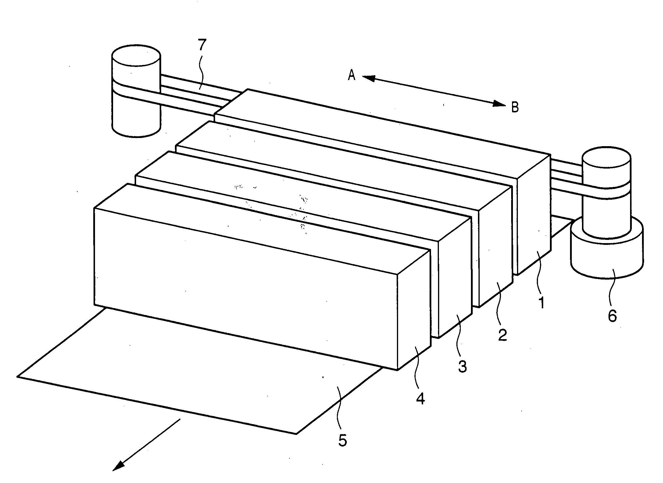
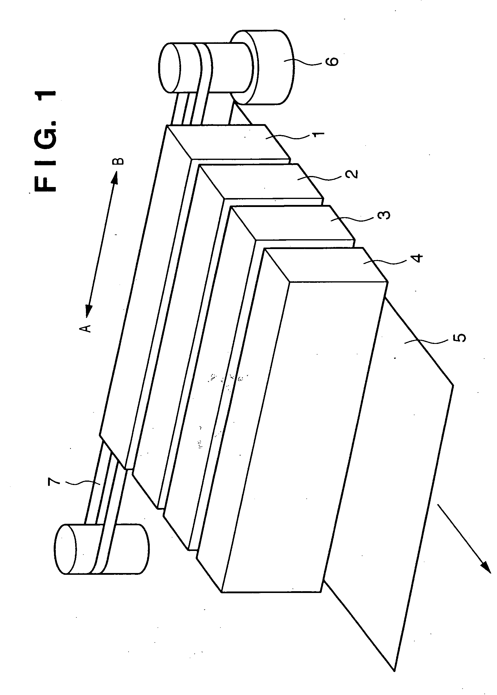
[0137] Printing is performed using the printing apparatus shown in FIG. 1 and the printhead 100 described in the first embodiment under the same condition settings as those in the first embodiment except the print image size and print medium size.

[0138] As the print medium, L-size inkjet photo glossy paper (Pro Photo Paper PR-101L: available from Canon) is used.

[0139] As the print image, a photographic image (to be referred to as image 2 hereinafter) is prepared, and the image is printed at a size of 89 m×127 mm on the above-mentioned paper sheet of the L size (89 mm×127 mm).

[0140] In the second embodiment, similar to the first embodiment, the image size is read, and nozzle groups for use are selected, as needed. The number of nozzles used to print image 2 is 4,205 (=89 mm / 25.4 mm×1,200 dpi), which is much smaller than the total number of effective nozzles (12,124 nozzles) of the printhead.

[0141]FIG. 15 is a view schematically showing the relationship between the printhead and t...

third embodiment

[0150]FIG. 17 is an outer perspective view showing the schematic arrangement of a printing apparatus adopted in the third embodiment. In FIG. 17, the same reference numerals as those in the first embodiment denote the same parts, and a description thereof will be omitted.

[0151] The characteristic arrangement of the printing apparatus shown in FIG. 17 is a paper supply unit 8 which fixes the print medium supply position in advance in accordance with the size of a print medium for use.

[0152] The paper supply unit 8 sets the print medium fixing position so that portions printed by the connected portions between chips which form the printhead are located at visually least perceivable positions on a print medium. For this reason, the position of a print medium in the paper supply unit 8 is uniquely determined by selecting the size of a print medium for use.

[0153] In the third embodiment, printing is performed using a printing apparatus having the above arrangement under the same condi...


PUM


Abstract

This invention relates to a printing apparatus and printing method which can stably print at high image quality on print media of various sizes by using a full-line printhead. The printing method uses a full-line printhead which has a long printing width and is configured by arraying a plurality of substrates each prepared by arraying a plurality of printing elements and each having a given printing width. When printing is done by conveying a print medium in a direction different from the array direction of the printing elements having the long printing width, printing elements used for printing are selected in accordance with an input image printing width so that an area printed on the print medium by printing elements corresponding to the connected portions between the substrates becomes a visually least perceivable area on the print medium. The relative moving amount of the full-line printhead to the print medium is so determined as to print by using the selected printing elements. The relative position of the full-line printhead is moved by the determined relative moving amount, and printing is done using the selected printing elements at the position after movement.

Description

FIELD OF THE INVENTION [0001] This invention relates to a printing apparatus and printing method and, more particularly to an inkjet printing apparatus and printing method using a full-line printhead whose printing width covers the width of a print medium. BACKGROUND OF THE INVENTION [0002] A printing apparatus used as a printer, copying machine, or the like, or a printing apparatus used as an output device for a multifunction electronic apparatus or workstation including a computer and wordprocessor prints an image (including characters, symbols, and the like) on a print medium such as a paper sheet or thin plastic plate on the basis of printing information. Such printing apparatuses are classified by the printing method into an inkjet type, wire dot type, thermal type, laser beam type, and the like. [0003] In a so-called serial type printing apparatus which performs printing operation while scanning a printhead in a direction (main scanning direction) perpendicular to the print me...

Claims


Application Information

Patent Timeline
IPC IPC(8): B41J2/01B41J2/155
CPCB41J2202/20B41J2/155B41J25/001
Inventor YAMAGUCHI, HIROMITSUWADA, SATOSHIAKAHIRA, MAKOTO
Owner CANON KK
Why Eureka
Try Eureka