Monitor system for monitoring suspicious object

a technology for monitoring suspicious objects and monitor cameras, which is applied in the field of monitor systems, can solve the problems of increasing the cost of installing the devices, requiring an additional cost of monitor cameras and various connection devices, and sometimes having a resolution too low to be useful, and achieves the effect of high monitoring resolution

Inactive Publication Date: 2005-12-15
VICTOR CO OF JAPAN LTD
View PDF1 Cites 134 Cited by
  • Summary
  • Abstract
  • Description
  • Claims
  • Application Information

AI Technical Summary

Benefits of technology

[0020] In view of the foregoing, it is an object of the present invention to provide a low-cost configuration monitor system capable of enlarging one or more monitor objects, which appear in a monitor area, at a high resolution for monitoring.

Problems solved by technology

However, they are conflicting requirements.
That is, if an event requiring careful attention occurs in a place where a single monitor camera is installed to cover a wide range, the part of a video requiring careful attention sometimes has a resolution that is too low to be useful.
On the other hand, many monitor cameras, if installed per unit area, would require an additional cost of not only the monitor cameras but also various connection devices and recording devices and, in addition, increase the cost for installing those devices.
However, such an object tracking-type video camera system is required to do the wide-angle operation and the telescopic operation repeatedly to continuously capture a moving object and, so, its tracking performance is not so high.
In addition, an extreme zoom operation, if performed for an object, makes a security guard fail to identify the relative location of the object relative to the background video (monitor area) and puts the security guard into confusion.
However, when a wide-angle camera and a tracking camera are used as separate cameras to track one object, they tend to generate an accuracy problem in the tracking control signal supplied from the wide-angle camera to the tracking camera.
That is, unless the optical axes of the lenses of the two cameras almost coincide, the object coordinate information given to the tracking camera does not always match the coordinate information on the wide-angle camera and, therefore, the object cannot be captured accurately.
In addition, because there are many practical problems including the limitation on the installation location, it is not easy to determine the installation location satisfying the desired operation conditions.
Therefore, in such an environment, the object tracking-type monitor video camera system described above, which basically assumes only one object to be tracked, cannot achieve the object.
However, considering the costs of the monitor cameras, camera connection devices, and recording devices as well as the installation cost of those devices, providing a plurality of tracking cameras would greatly increase the cost of the whole system with the result that building such a system becomes impractical.
However, such a system generates a huge amount of information and makes it difficult to monitor and record information for a long time.
However, this technology is not related to a monitor device and, therefore, does not suggest any solution for reducing the amount of image processing data in the technology for tracking a moving object.
Therefore, if an existing communication network is used, the problem is that the processing speed of the whole system is not increased due to the transmission capacity of the communication network even if a very high-precision sensor is used.
This increases the cost of the monitor side.

Method used


Image

  • Monitor system for monitoring suspicious object
  • Monitor system for monitoring suspicious object
  • Monitor system for monitoring suspicious object

Examples


first embodiment

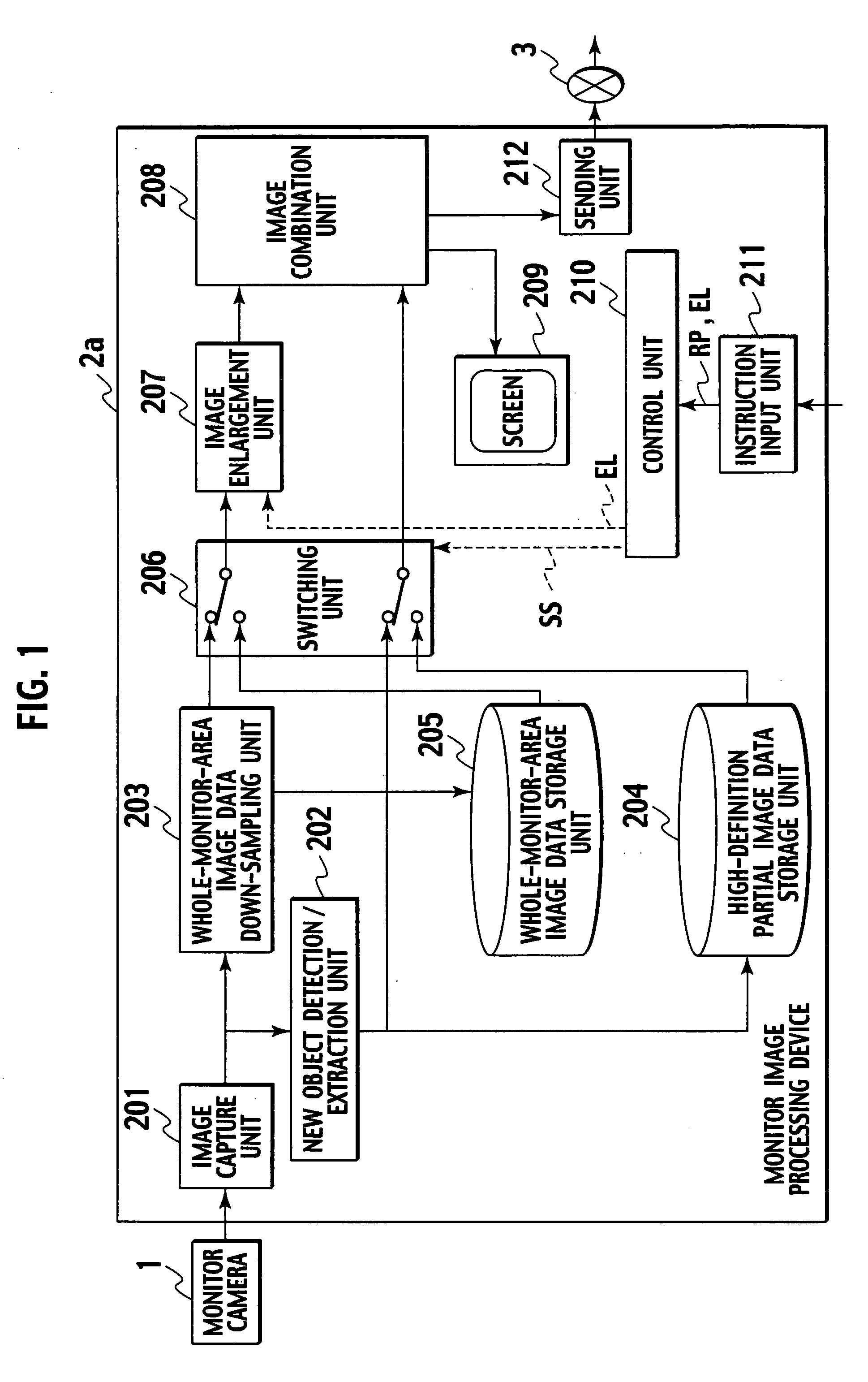
[0055]FIG. 1 is a diagram showing the configuration of a first embodiment of the monitor system according to the present invention.

[0056] The monitor system in the first embodiment comprises a monitor camera 1 that can photograph a monitor area and acquire the photographed data as high definition image data (1024 horizontal dots×768 vertical dots, 1600 horizontal dots×1200 vertical dots, 3200 horizontal dots×2400 vertical dots, etc.); and a monitor image processing device 2a that processes high definition image data, sent from the monitor camera 1, and displays it on display means.

[0057] The monitor image processing device 2a comprises an image capture unit 201 that captures high definition image data from the monitor camera 1; a new object detection / extraction unit 202 that detects a new object in a monitor area based on the high definition image data sent from the image capture unit 201, extracts the partial image data of an area, which contains a new object, from the high defin...

second embodiment

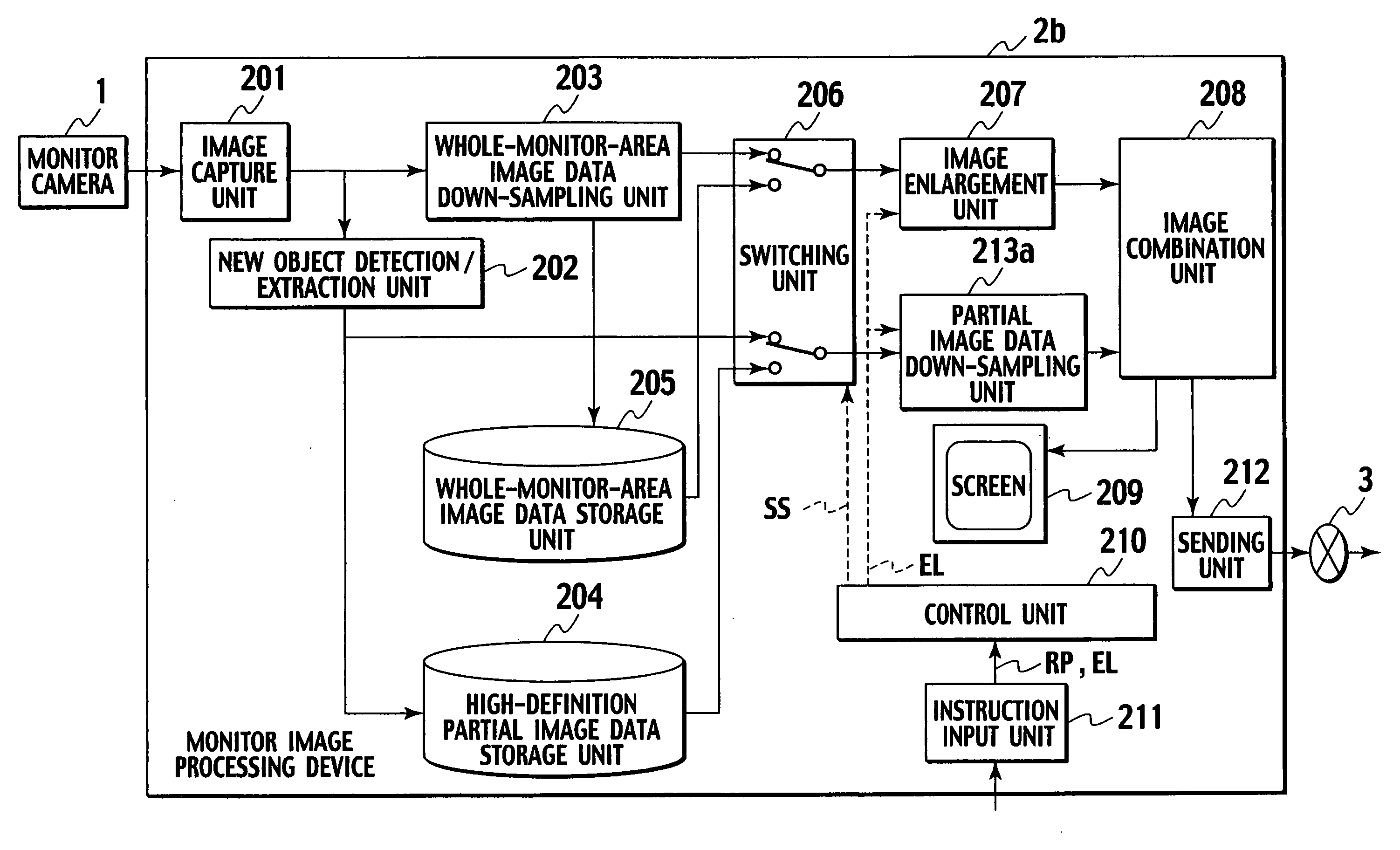
[0088]FIG. 7 is a diagram showing the configuration of a second embodiment of a monitor system according to the present invention.

[0089] The same reference numeral is used in the configuration shown in FIG. 7 to denote the same element of the configuration shown in FIG. 1, and further description of that element will be omitted.

[0090] The configuration of the second embodiment is different from the configuration shown in FIG. 1 in that a partial image data down-sampling unit 213a is added. The partial image data down-sampling unit 213a receives partial image data and scene description data, thins out (down samples) the partial image data, and outputs the processed image data to the image combination unit 208. In addition, the partial image data down-sampling unit 213a receives the enlargement instruction signal EL from the control unit 210.

[0091] The following describes the operation more in detail. The description given below is common to both the real-time processing and the re...

third embodiment

[0099]FIG. 9 is a diagram showing the configuration of a third embodiment of a monitor system according to the present invention.

[0100] The same reference numeral is used in the configuration shown in FIG. 9 to denote the same element of the configurations shown in FIG. 1 and FIG. 7, and further description of that element will be omitted.

[0101] In the second embodiment, the configuration where a continuously varying enlargement rate can be used is described. In that configuration, the high-definition partial image data storage unit 204 stores fully high definition images and, when an image is reproduced, a fully high definition image from the high-definition partial image data storage unit 204 is down-sampled according to a specified enlargement rate and is overlapped on an enlarged whole image.

[0102] In contrast, a third embodiment has a configuration where the enlargement rate is one of the predetermined values. That is, a partial image data down-sampling unit 213b is in a sta...


PUM


Abstract

A monitor camera photographs a whole monitor area for capturing the photographed whole monitor area as high definition image data higher in resolution than a display screen. A new object detection/extraction unit detects a new object in the monitor area based on the high definition image data captured by the monitor camera, extracts partial image data of an area, which contains the new object, from the high definition image data, and obtains location information on the partial image data in relation to the high definition image data. A whole-monitor-area image data down-sampling unit down-samples the high definition image data to produce standard definition image data corresponding to the resolution of the display screen. An image enlargement unit enlarges the standard definition image data based on entered enlargement instruction information. An image combination unit overlaps the partial image data on image data, enlarged by the image enlargement unit, based on the location information and sends resulting image data to the display screen.

Description

BACKGROUND OF THE INVENTION [0001] 1. Field of the Invention [0002] The present invention relates to a monitor system installed in a large store, a recreational facility, and so on, and more particularly to a low-cost configuration monitor system capable of enlarging one or more monitor objects, which appear in a monitor area, at a high resolution for monitoring. [0003] 2. Description of the Related Art [0004] A monitor video camera system in a large store or a recreational facility is required to cover a wide range with a smaller number of monitor cameras from the viewpoint of economy but is preferably required to have many monitor cameras per unit area from the viewpoint of monitoring accuracy based on detailed videos. [0005] However, they are conflicting requirements. That is, if an event requiring careful attention occurs in a place where a single monitor camera is installed to cover a wide range, the part of a video requiring careful attention sometimes has a resolution that is...

Claims


Application Information

Patent Timeline
Patent Type & Authority Applications(United States)
IPC IPC(8): G06T7/20H04N7/18H04N9/74
CPCG06T7/2053G08B13/19608H04N7/188H04N7/183G08B13/19691G06T7/254
Inventor ISHII, YUSUKE
Owner VICTOR CO OF JAPAN LTD
Why Eureka
Try Eureka