Variable focal length lens comprising micromirrors with one degree of freedom translation

a variable focal length and micro-mirror technology, applied in the field of variable focal length lenses comprising micro-mirrors, can solve the problems of complex driving mechanisms to control the relative positions of refractive lenses, slow response time, low focusing efficiency, etc., to achieve simple mechanical structures and actuating components, increase the effective reflective area, and reduce the effect of aberration

Active Publication Date: 2005-12-15
STEREO DISPLAY
View PDF8 Cites 11 Cited by
  • Summary
  • Abstract
  • Description
  • Claims
  • Application Information

AI Technical Summary

Benefits of technology

This patent describes a new type of lens made up of tiny mirrors called micromirrors. These mirrors move back and forth in two directions (translation) to create different focus positions. By controlling these movements separately, researchers have been able to make this lens more accurate and efficient compared to traditional lenses. The use of smaller mirrovers makes it easier to achieve high levels of accuracy. Additionally, advanced technology allows for the replacement of electrical circuitry with better performing semiconductor materials like MOS and CMOS. Overall, this innovative design offers greater flexibility and precision when adjusting the lens's performance.

Problems solved by technology

This patent describes an improved design for a variable focal length lens that uses micro mirrors instead of traditional refractive lenses. However, current designs require complicated machining processes and lack efficient focus adjustment. There is also a problem with slow response times when controlling the lens's position. In summary, there is a technical problem in developing a simpler and faster acting micromirror array lens with just translational movement without requiring excessive machine tools or having poor focus adjustability.

Method used


Image

  • Variable focal length lens comprising micromirrors with one degree of freedom translation
  • Variable focal length lens comprising micromirrors with one degree of freedom translation
  • Variable focal length lens comprising micromirrors with one degree of freedom translation

Examples


Embodiment Construction

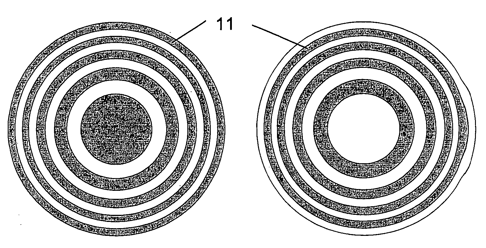
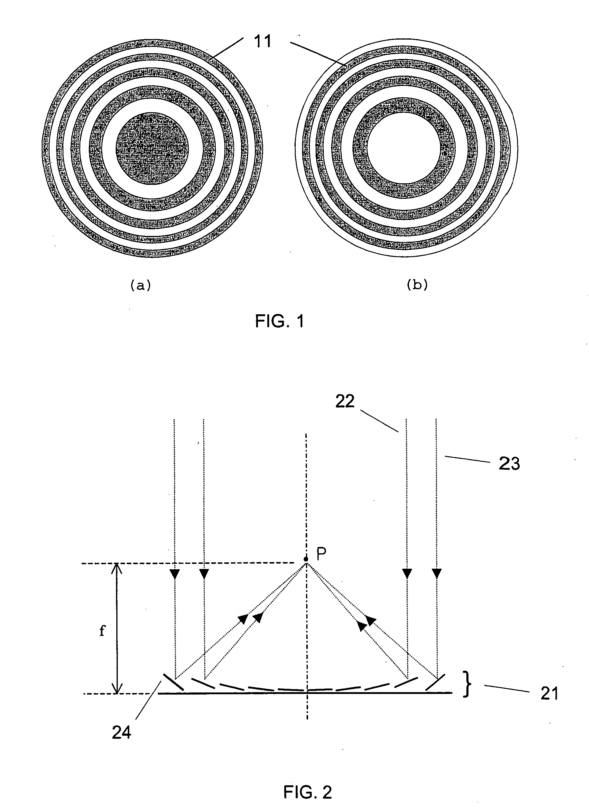
[0037]FIG. 1 shows zone plates. Gray regions (zones) 11 are the area where lights are blocked. In FIG. 1(a), the left plate, light blocked at even zones and in FIG. 1(b), the right plate, lights are blocked at odd zones. But two plate have same focus and intensity. Every zone have the same area and optical path length (OPL) difference between from every adjacent zones to focal point is half wavelength. Focal length is changed by changing the width of zone.

[0038]FIG. 2 illustrates the principle of the conventional micromirror array lens. There are two conditions to make a perfect lens. The first is the converging condition that all light scattered by one point of an object should converge into one point of the image plane. The second is the same phase condition that all converging light should have the same phase at the image plane.

[0039] A micromirror array arranged in flat plane can satisfy two conditions to be a lens. Each of the micromirrors rotates to converge the scattered li...


PUM


Abstract

A variable focal length lens comprising micromirrors with pure translation is invented. The lens consists of many micromirrors and actuating components. The array of micromirrors with pure translation makes all lights scattered from one point of an object have the same periodic phase and converge at one point of image plane by using Fresnel diffraction theory. The actuating components control the positions of micromirrors electrostatically and/or electromagnetically. The optical efficiency of the micromirror array lens is increased by locating a mechanical structure upholding micromirrors and the actuating components under micromirrors. The known semiconductor microelectronics technologies can remove the loss in effective reflective area due to electrode pads and wires. The lens can correct aberration by controlling each micromirror independently. Independent control of each micromirror is possible by known semiconductor microelectronics technologies. The micromirror array can also form arbitrary shape and/or size of a lens.

Description


Claims


Application Information

Patent Timeline
Owner STEREO DISPLAY
Why Eureka
Try Eureka