Candle arrangement

a technology for candles and votives, applied in portable electric lighting, lighting and heating devices, lighting support devices, etc., can solve the problems of difficult and time-consuming replacement of burned candles, increased weight of assembled candles and votives, and increased cost of candles

Active Publication Date: 2005-12-15
LOFTS ANDREW
View PDF13 Cites 7 Cited by
  • Summary
  • Abstract
  • Description
  • Claims
  • Application Information

AI Technical Summary

Benefits of technology

[0012] A plurality of burning candles are movably positioned in the tubular member for sliding motion therein. Each of the plurality of burning candles has a tubular case and a base member spaced from the bottom edge of the tubular case to define a separating ring of the tubular case between the base and the end of the tubular case. The inside of the tubular case is provided with a wick fixed to the inside of the base and extending upwardly therefrom and the inside of the tubular case is filled with a burning candle wax which may be of conventional composition but has a melting point lower than the melting point of the main candle body so that the burning of the burning candle does not melt the main candle body.

Problems solved by technology

The votive was often made of glass and this increased the weight of the assembled candle and votive.
Since the votive or shell could be decorated in as fancy or attractive fashion as desired by the inclusion of colored materials such as pebbles, beans, candies or the like, the cost of such a shell or votive often exceeded the cost of the candle itself.
However, removing the burned candle to allow the replacement thereof by a new candle often was difficult and time consuming.
Further, the provision of only one smaller candle placeable in the shell at any one time limited the usefulness of such candles.

Method used


Image

  • Candle arrangement
  • Candle arrangement
  • Candle arrangement

Examples


embodiment 10

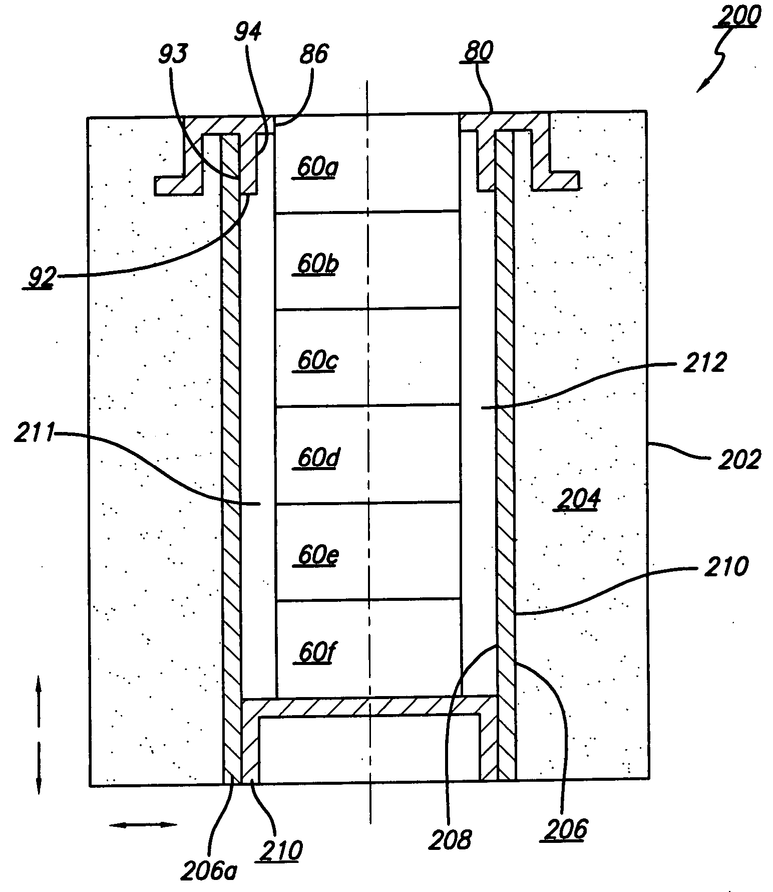
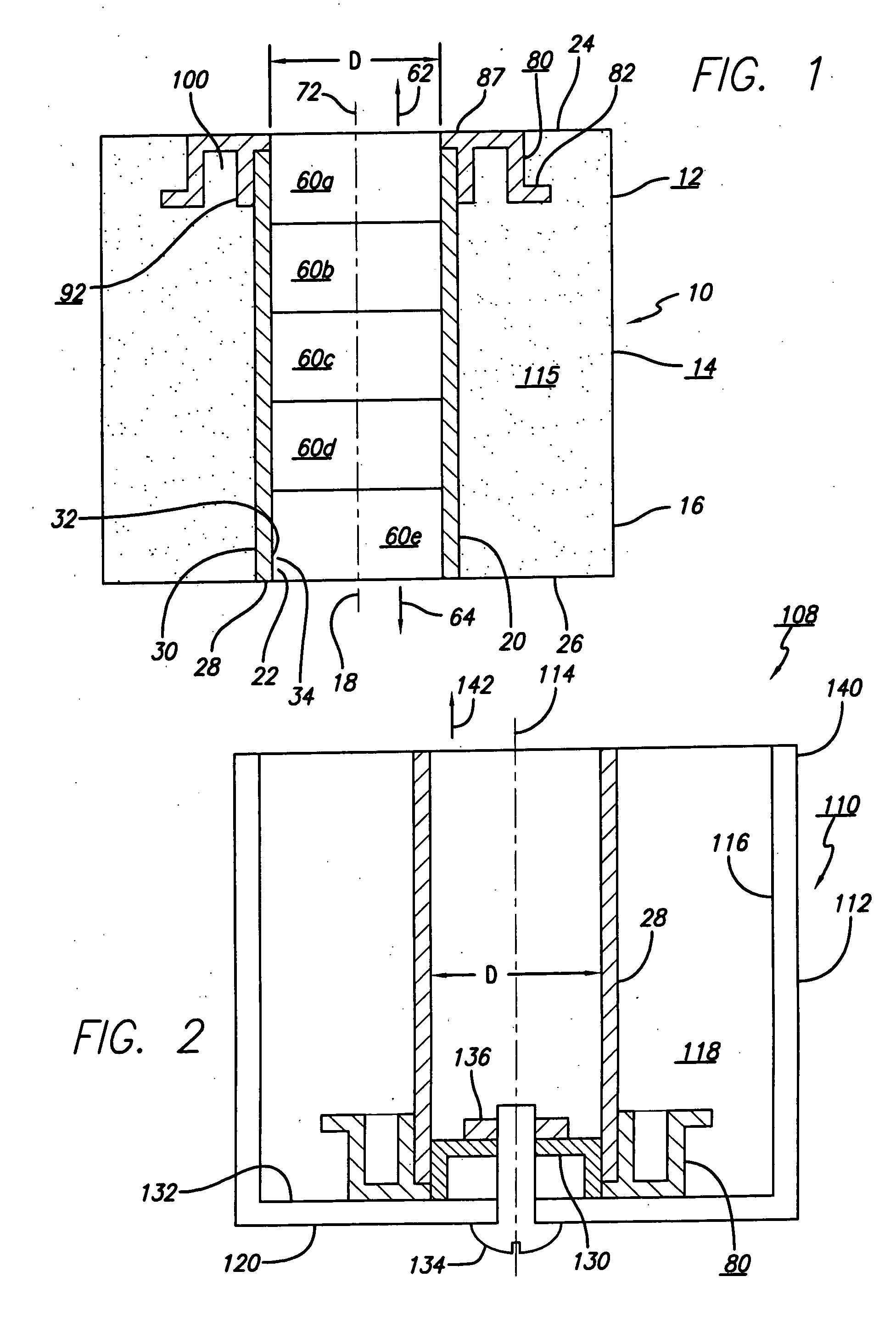
[0042] In utilizing the candle arrangement 12 of embodiment 10 as shown on FIG. 1, the plurality of burning candles 60a, 60b, 60c, 60d and 60e are inserted into the candle receiving aperture 34 defined by the tubular member 28 in either direction indicated by the arrows 62 and 64. When properly aligned, the wick 72 of the upper most burning candle 60a is lit and the candle may continue to burn until the wax 72 thereof is consumed. The consumed burning candle 64a may be ejected from the candle receiving aperture 34 by pressing upwardly in the direction of the arrow 62 on the lowest burning candle 60e until the burning candle 60b is properly positioned. A new burning candle may then be placed in the in the space previously occupied by the burning candle 64e. Alternatively, the consumed burning candle 60a may be pressed downwardly in the direction indicated by the arrow 64 until the burning candle 60e is ejected. The burning candle 60e may then be placed in the position previously occu...

embodiment 220

[0051]FIG. 8 illustrates another preferred embodiment 220 of a candle arrangement 222 which is generally similar to the embodiments 10 and 200 described above. The candle arrangement 222 has a main candle body 223 which is generally similar to the main candle bodies 14 and 204 described above. The candle arrangement 222 has a retainer 224 generally similar to the retainer 80 described above but does not have the shoulder portion 87 described above. A tubular member 225 is positioned against the inner downwardly depending tube portion 229 and extends to the top surface 222a of the main candle body 223. The embodiment 220 may be operated in a manner similar to that described above in connection with FIG. 1.

[0052] If desired, a second tubular member 228 shown in dashed lines may be positioned in the retainer 225 in a manner as described above in connection with embodiment 220 the second tubular member 228 has inner walls 231 spaced from the first tubular member 225 to define a first ai...


PUM


Abstract

A candle arrangement having a main candle body having a relatively high melting point and the main candle body has an aperture therethrough and a plurality of burning candles having a candle wax with a lower melting point than the main candle body are slidably mounted in the aperture. The burning candle at the top of the main candle body may be burned and then discarded after it is consumed and replaced with a new burning candle.

Description

BACKGROUND OF THE INVENTION [0001] 1. Field of the Invention [0002] This invention relates to the candle art and more particularly to an improved decorative multiple candle configuration and the method of making the multiple candle configuration. [0003] 2. Description of the Prior Art [0004] Candles are often presently utilized both for light and for decorative purposes. Many varieties of decorative candles have been produced in the past. One technique for providing a decorative candle has been to place a candle in a shell or votive. The votive was often made of glass and this increased the weight of the assembled candle and votive. Such candle assembles were often only used once and the votive was discarded after the candle was burned. Since the votive or shell could be decorated in as fancy or attractive fashion as desired by the inclusion of colored materials such as pebbles, beans, candies or the like, the cost of such a shell or votive often exceeded the cost of the candle itse...

Claims


Application Information

Patent Timeline
Patent Type & Authority Applications(United States)
IPC IPC(8): F21L19/00F21V35/00
CPCF21V35/00
Inventor DENNIS, JOHN D.URFIG, BERNARD
Owner LOFTS ANDREW
Why Eureka
Try Eureka