
Transferring compression parameters in a mobile communication system

Inactive Publication Date: 2005-12-15
NOKIA SOLUTIONS & NETWORKS OY
View PDF6 Cites 35 Cited by
  • Summary
  • Abstract
  • Description
  • Claims
  • Application Information

AI Technical Summary

Benefits of technology

[0041] The benefits of the invention are associated with improved reliability of data transmission to and from a mobile node. With the invention it is now possible to provide a uninterrupted packet data connection to a mobile node even as the mobile node changes from an area controlled by a first packet switching node to an area controlled by a second packet switching node. The packet data connection is no longer terminated, if the second packet switching node proposes other compression parameters than previously used.

Problems solved by technology

A disadvantage associated with wireless data transmission is that the data transfer rate is limited compared to wire-line data transmission.
Especially, the data transfer rate is limited in cellular mobile communication systems where a given frequency band must be shared by a number of simultaneous users.
The problem is made worse in the cases where IP-in-IP tunneling is used, for example, in association with the Mobile IP.
The ABM release that is performed in association with the processing of XID Reset parameter specified in the XID Command message causes significant problems in prior art.
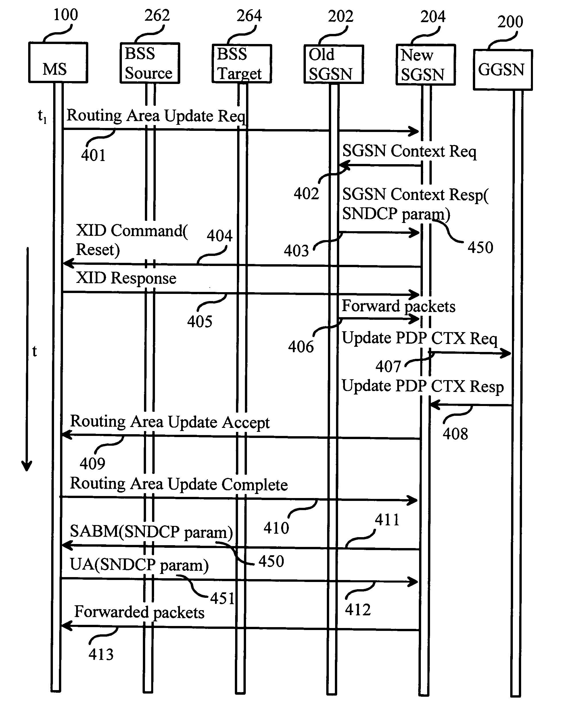
However, without knowledge of the previously used SNDCP parameters there is no possibility to re-establish the ABM mode with the SNDCP parameters that were used by the old SGSN, namely SGSN 202, to communicate with MS 100.
There are three problems related to this.
Secondly, if SGSN 204 proposes any compression entities there is no guarantee that MS 100 is capable of changing them.
Some mobile stations do not work properly in the first case and some do not work properly in the second and third cases.

Method used


Image

  • Transferring compression parameters in a mobile communication system
  • Transferring compression parameters in a mobile communication system
  • Transferring compression parameters in a mobile communication system

Examples


Embodiment Construction

[0049] Reference will now be made in detail to the embodiments of the present invention, examples of which are illustrated in the accompanying drawings.

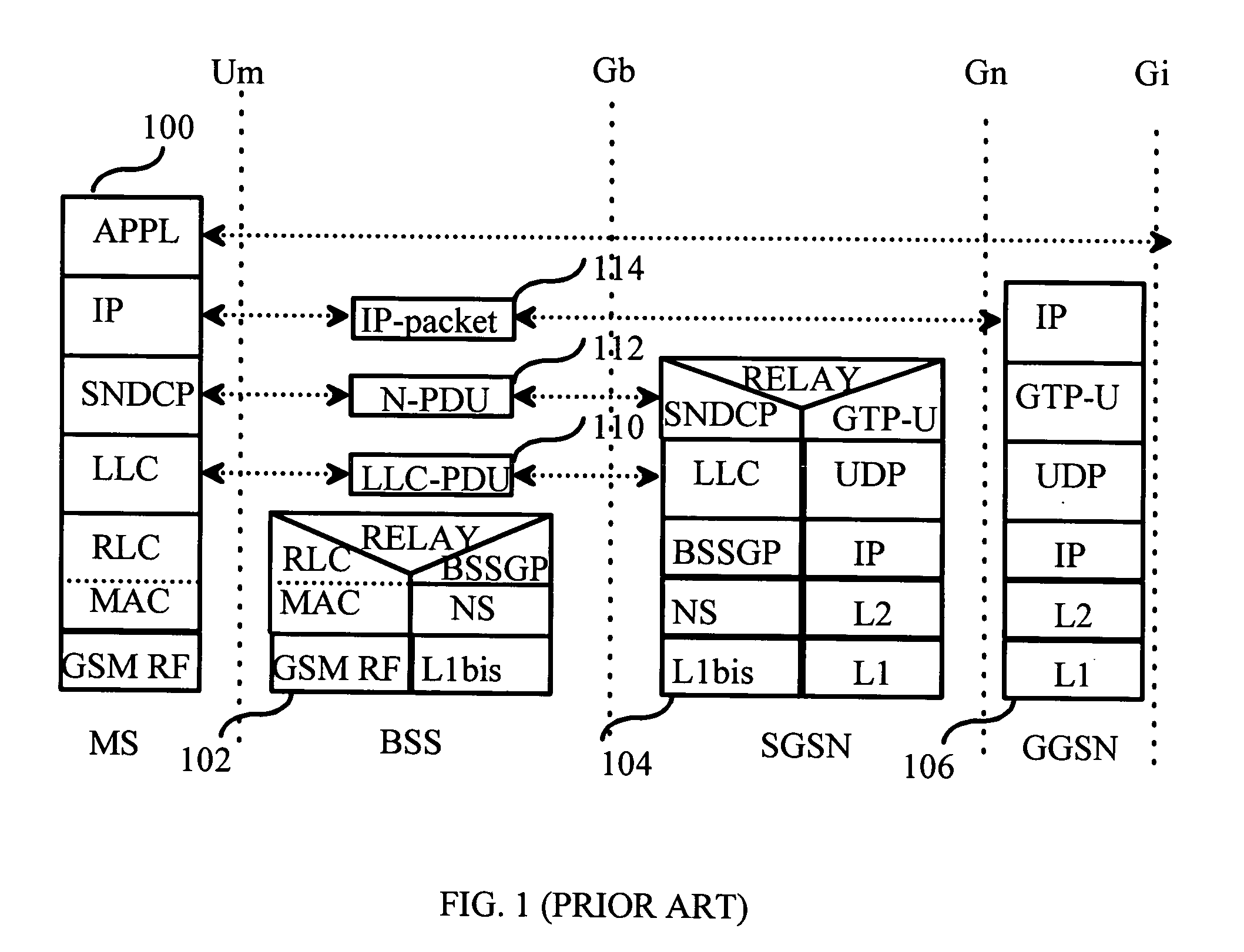
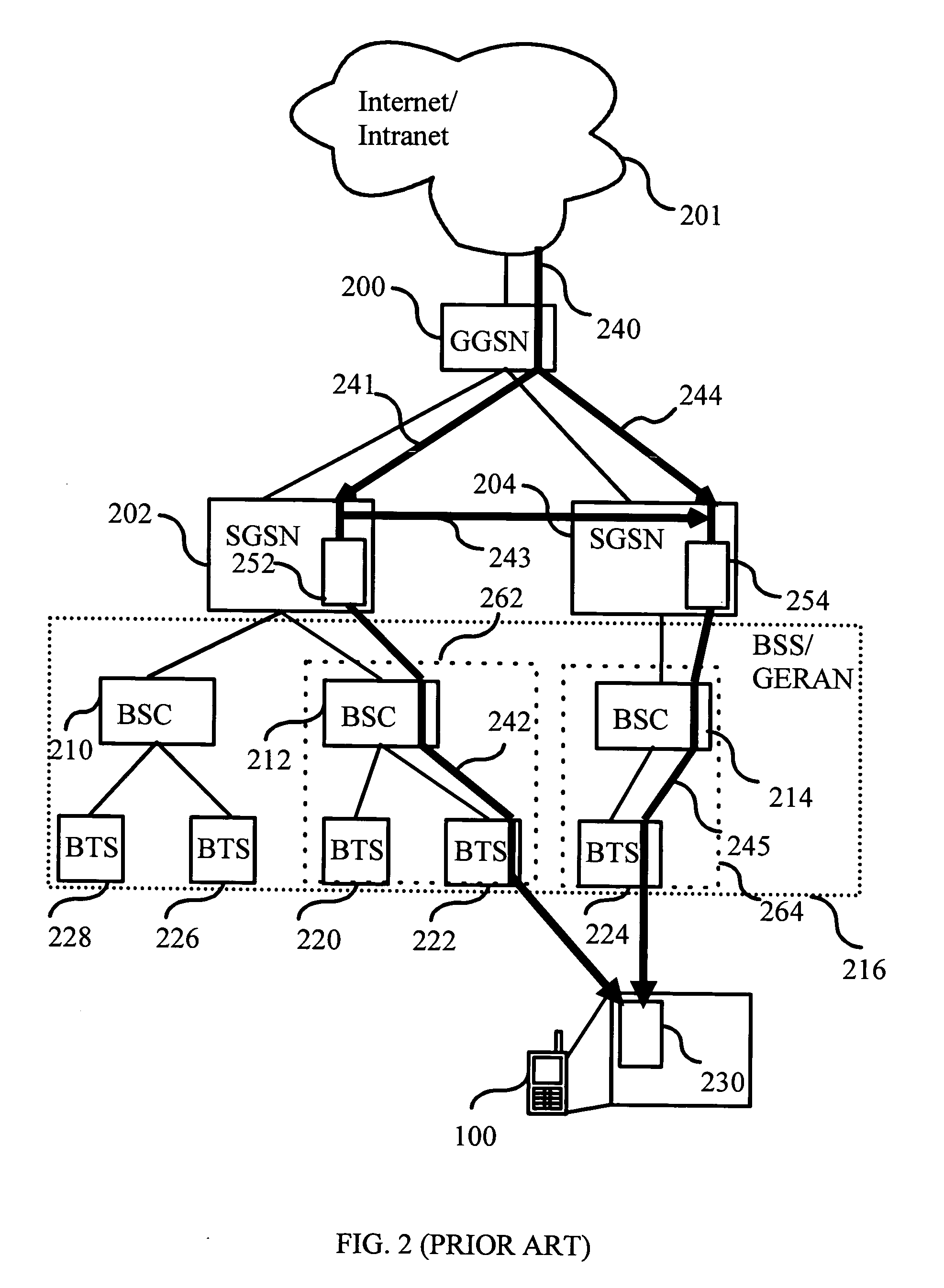
[0050]FIG. 5 is a flow chart depicting one embodiment of a method for compression parameter transfer, which utilizes a routing area update signaling as illustrated in FIG. 4. The signaling is performed in the GPRS system architecture, which is illustrated in FIGS. 1 and 2. At step 500 a MS 100 waits for Routing Area (RA) update condition. RA update condition is fulfilled as MS 100 detects an event that indicates that it must start using a new cell (not shown). The new cell is within a new routing area, which is controlled by a new SGSN 204. MS 100 sends a Routing Area Update Request message to SGSN 204 as illustrated with arrow 401. Thereupon, the method continues at step 502.

[0051] At step 502 SGSN 204 sends an SGSN Context Request message illustrated with arrow 402 to SGSN 202 to get the mobility management and PDP contexts for M...


PUM


Abstract

The invention relates to a method for transmitting compression parameters in a mobile communication system, comprising a mobile node, a first and a second packet switching node. In the method the second packet switching node is informed of the entry of the mobile node to an area controlled by the second packet switching node. At least one compression parameter is received from the first packet switching node to the second packet switching node. The second packet switching node informs at least one of the at least one compression parameter to the mobile node by way of layer-3 parameter renegotiation for a logical link connection. The benefits of the invention are related to improved reliability of packet data transmission to and from a mobile node.

Description

BACKGROUND OF THE INVENTION [0001] 1. Field of the Invention [0002] The invention relates to mobile communication systems. Particularly, the invention relates to the transfer of packet header and data compression parameters in a mobile communication system. [0003] 2. Description of the Related Art [0004] A disadvantage associated with wireless data transmission is that the data transfer rate is limited compared to wire-line data transmission. Especially, the data transfer rate is limited in cellular mobile communication systems where a given frequency band must be shared by a number of simultaneous users. When transferring packet data in a cellular mobile communication system, the data transfer rate made available for application layer data transmission is further reduced due to frame and packet headers. For example, when the Transmission Control Protocol (TCP) is carried over the Internet Protocol (IP) version 4, the total header size is 40 bytes of which TCP layer headers take 20 ...

Claims


Application Information

Patent Timeline
IPC IPC(8): H04LH04L12/56H04L29/06H04W36/08H04W36/12
CPCH04W36/0055H04W28/06
Inventor HEIMAN, MIKATURUNEN, JYRI
Owner NOKIA SOLUTIONS & NETWORKS OY
Learn More