Remotely operated deployment system and method of use

a deployment system and remote operation technology, applied in the direction of cables, underwater equipment, instruments, etc., can solve the problems of complicated systems, limited amount of cables to be carried into place, and high cost of us

Inactive Publication Date: 2005-12-15
OCEANEERING INTERNATIONAL
View PDF12 Cites 96 Cited by
  • Summary
  • Abstract
  • Description
  • Claims
  • Application Information

AI Technical Summary

Problems solved by technology

Use of palletized reels and made-up connectors may complicate these systems and make them expensive to use.
The amount of cable which can be carried into place is limited in such configurations

Method used


Image

  • Remotely operated deployment system and method of use
  • Remotely operated deployment system and method of use
  • Remotely operated deployment system and method of use

Examples


Embodiment Construction

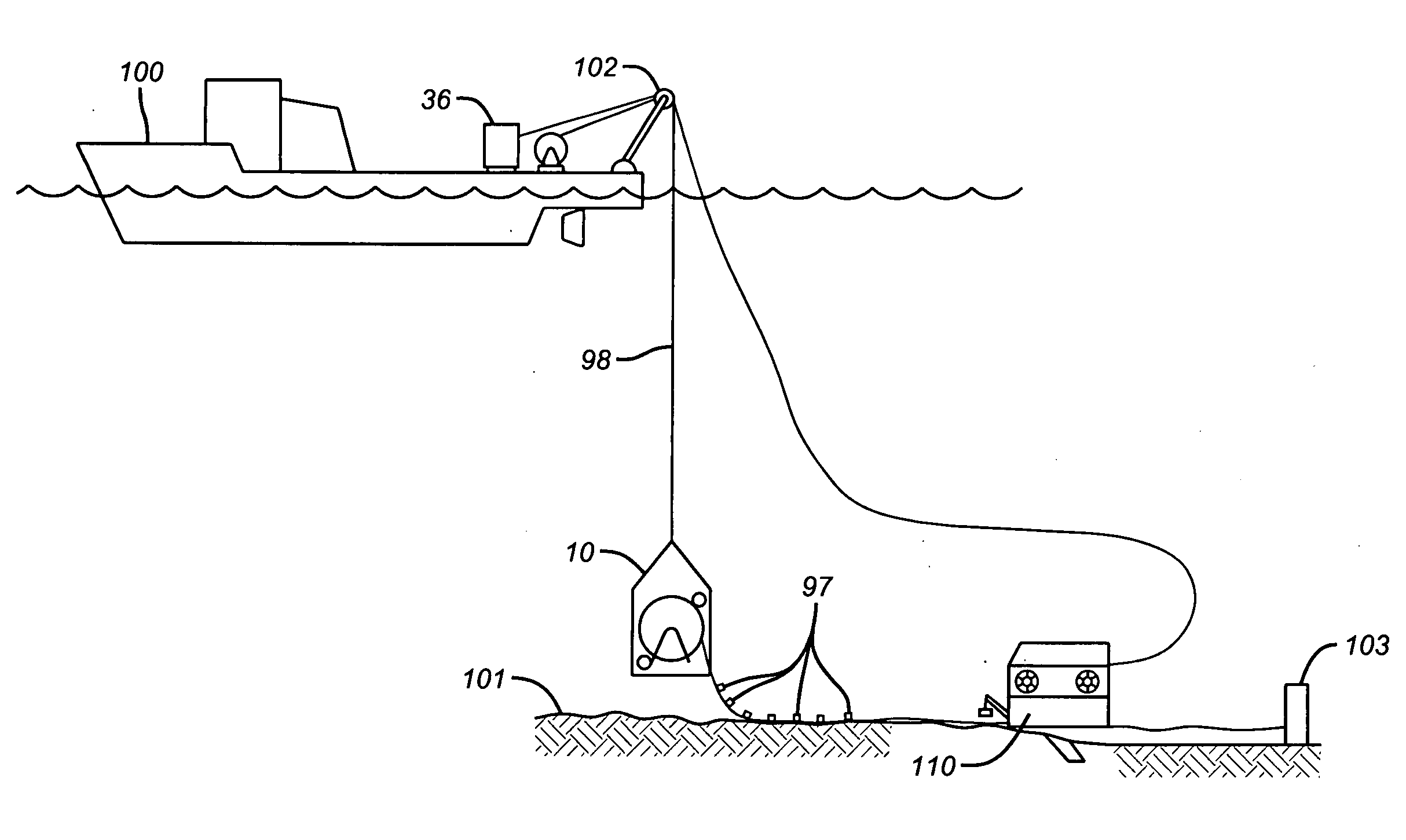
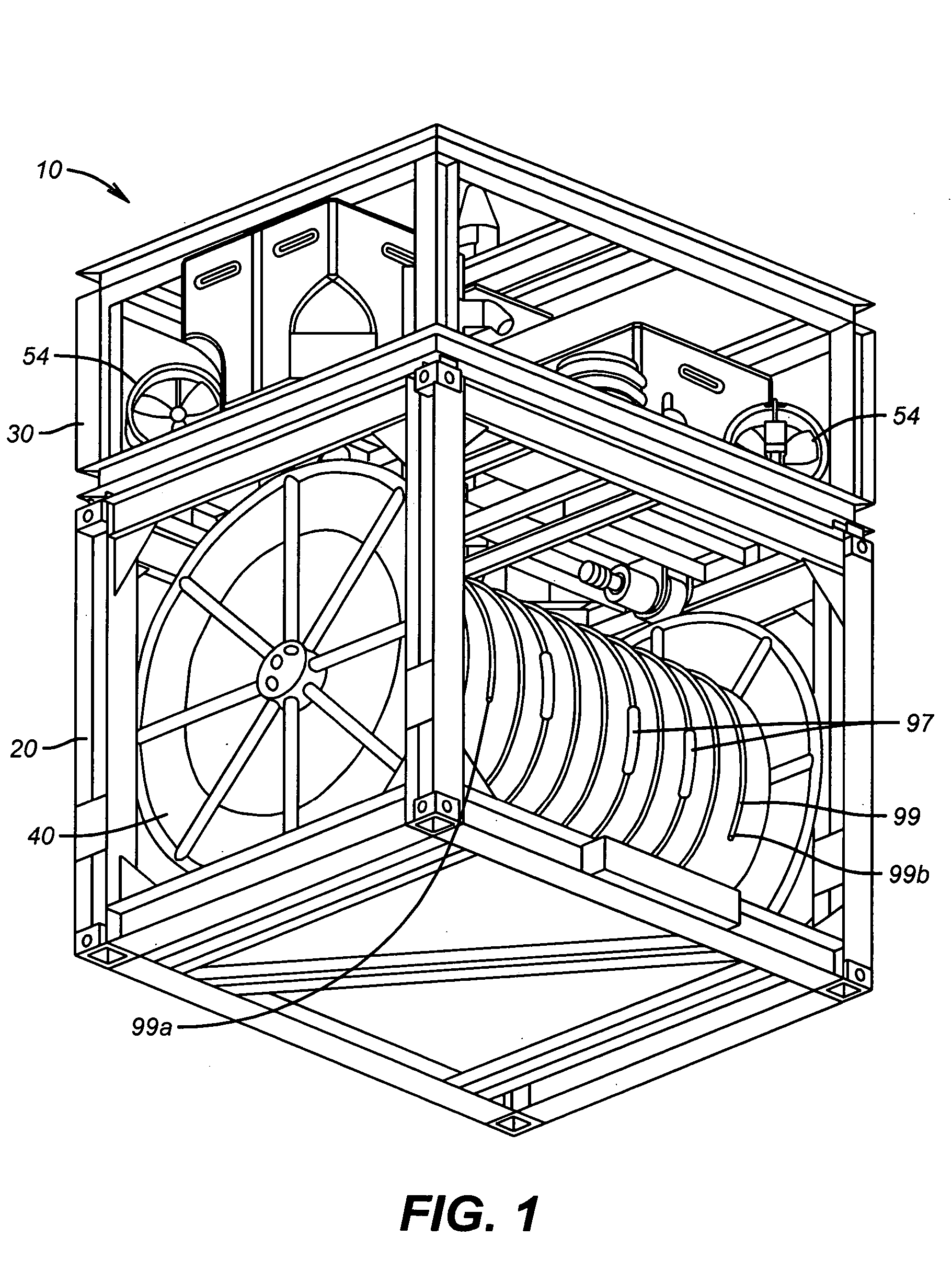
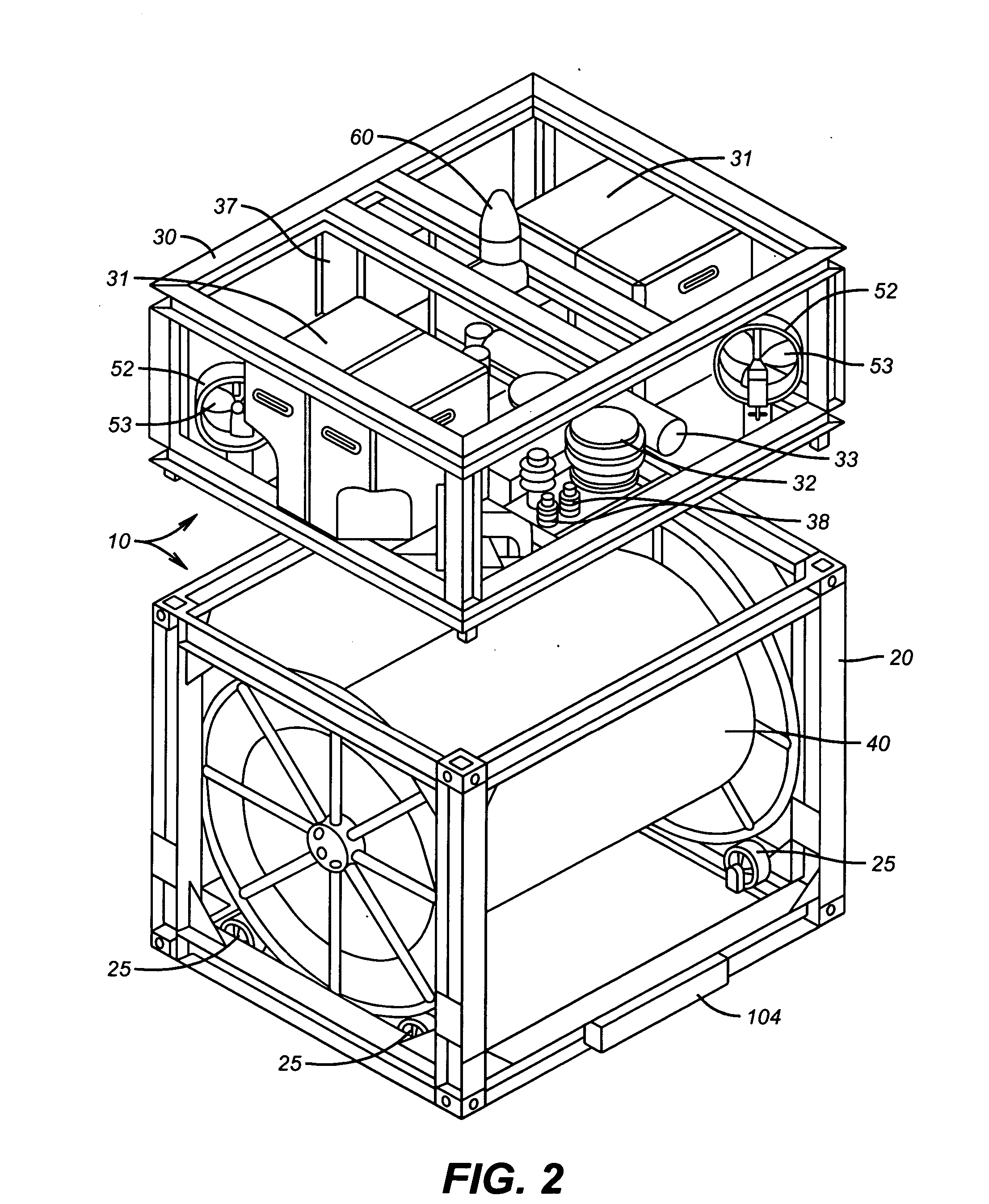
[0013] Referring now to FIG. 1 and FIG. 2, in an embodiment a remotely operated deployment system comprises cage 10, communications link 12 (not shown in the figures), and reel 40 rotatably and removably mounted within cage 10.

[0014] Cage 10 may be a unitary or multiple component unit and is typically constructed using steel welded, bolted, and / or pinned together. Cage 10 is typically around 140-160 inches in height, around 90-110 inches wide, around 110-130 inches in length, and constructed using a structural steel frame with a three pack epoxy paint coating.

[0015] Cage 10 may further comprise guidance system 35 (not shown in the figures) adapted to be remotely operable subsea by a vessel, e.g. surface vessel 100 (FIG. 4).

[0016] Cage 10 may further comprise hydraulic power unit 33 and / or electrical power unit 37, each adapted for use underwater at a predetermined depth. In a preferred embodiment, the depth may be as much as around 10,000 feet and cage 10 may be adapted to suppor...


PUM


Abstract

A system and method for deploying and/or retrieving a cable underwater. In an embodiment, a system comprises a cage, comprising a guidance system adapted to be remotely operable subsea by a vessel; a communications link operatively linking the guidance system and the vessel; and a non-palletized reel rotatably and removably mounted within the cage, the reel adapted to receive an unspoolable length of cable, the cable comprising two fee ends. In an exemplary method, the reel, onto which cable is spooled is removably and rotatably housed in a cage adapted for remote control use underwater and the cage lowered by a vessel to a position proximate a seafloor. The cage is maneuvered along a predefined flight pattern in substantially a single plane with respect to the seafloor while selectively releasing the cable from the reel. It is emphasized that this abstract is provided to comply with the rules requiring an abstract which will allow a searcher or other reader to quickly ascertain the subject matter of the technical disclosure. It is submitted with the understanding that it will not be used to interpret or limit the scope of meaning of the claims.

Description

RELATED APPLICATIONS [0001] This application claims priority from United States Provisional Application 60 / 489,705 filed Jul. 24, 2003.FIELD OF INVENTION [0002] The present invention relates to deployment of cables and other lines subsea. BACKGROUND OF THE INVENTION [0003] Cables are often deployed underwater for numerous reasons. For example, in certain uses seismic cables may be arranged, e.g. in an array or other pattern, for use subsea. Cables for such deployment may be pre-wound on a set of reels where the reels are either on pallets underwater or on a remotely operated vehicle (ROV). Often, all cable connections are made up prior to deployment and placed upon a pallet that is delivered to the desired field of investigation. The pallets preferably include all equipment (distribution hubs, communication riser, etc.) that are needed to communicate with the cables and are delivered to the ocean floor by a crane or other lowering device with the individual sensor array cables on re...

Claims


Application Information

Patent Timeline
IPC IPC(8): B63C11/42E21BF16L1/00F16L1/028F16L1/16
CPCB63C11/42G01V1/3852H02G1/10F16L1/16
Inventor ENTRALGO, ROGER D.SHAW, MICHAEL NEILL
Owner OCEANEERING INTERNATIONAL
Why Eureka
Try Eureka