
Sampling device

Inactive Publication Date: 2005-12-15
THE CLEVELAND CLINIC FOUND
View PDF9 Cites 24 Cited by
  • Summary
  • Abstract
  • Description
  • Claims
  • Application Information

AI Technical Summary

Benefits of technology

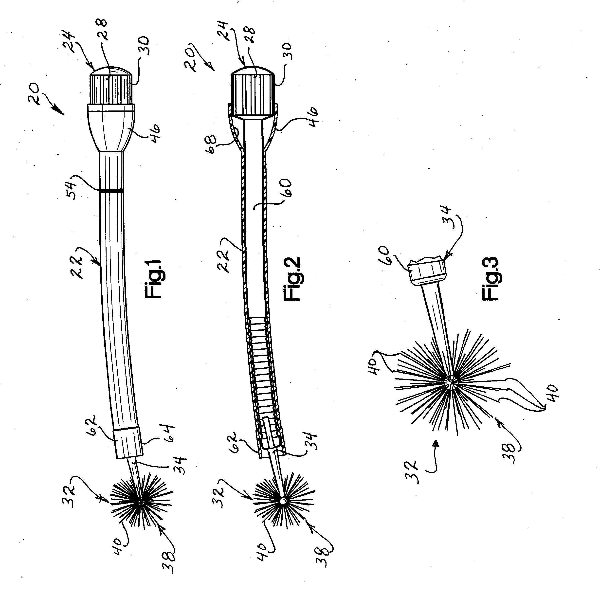
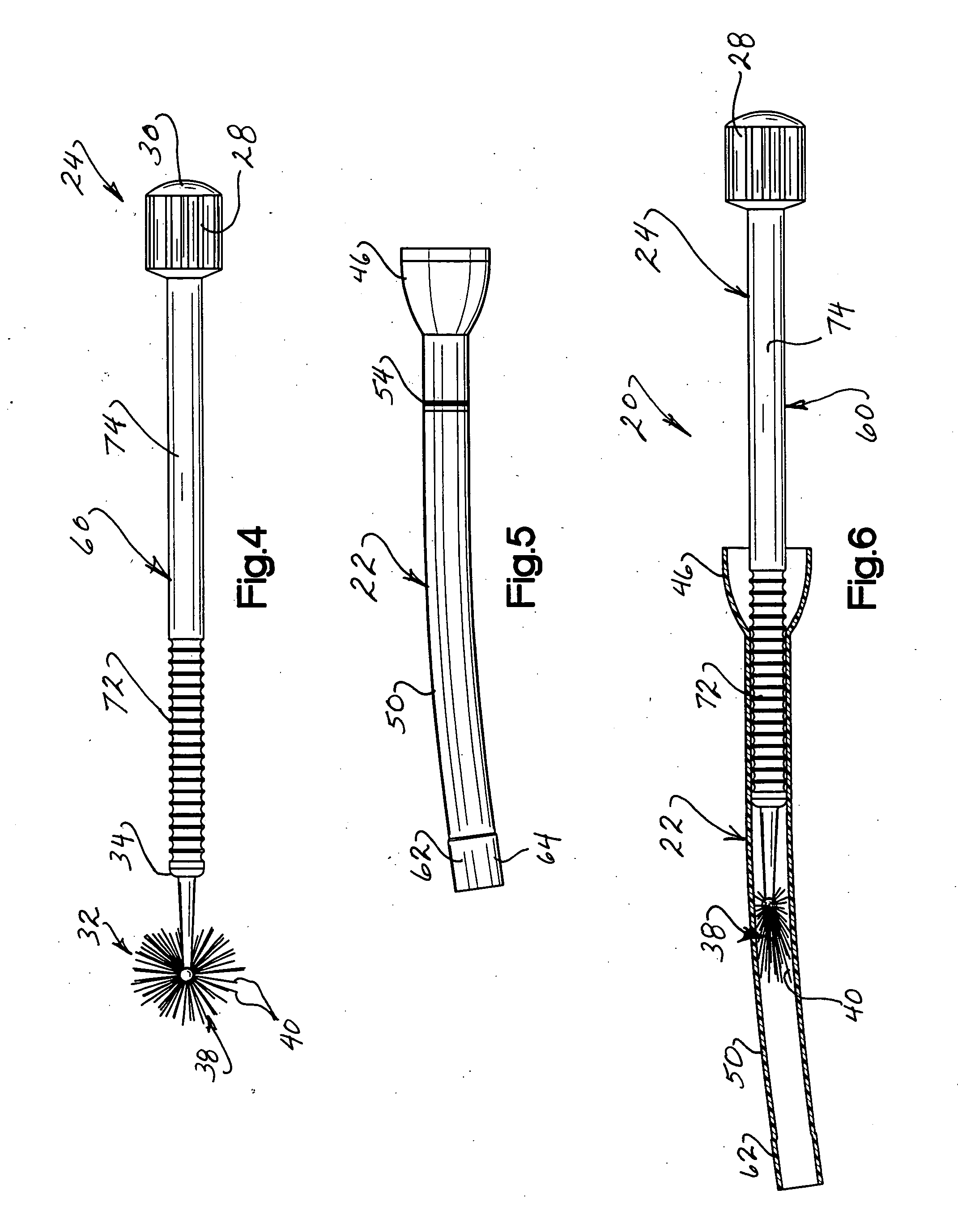
[0009] The distal end portion of the sampler may include a brush. The brush may have bristles with end portions which are arranged in a configuration corresponding to the configuration of at least a portion of a sphere. The brush is connected with the handle by a shaft having a length which is the greater than the length of the sheath. When the apparatus is in a retracted condition prior to insertion into a woman's reproductive system, a portion of the shaft extends outward from the proximal end portion of the sheath so that the handle is spaced from the proximal end portion of the sheath and the brush is at least partially enclosed by the sheath. After the sheath has been inserted into the woman's reproductive system, the sampler is axially movable relative to the sheath from a retracted position to an extended position to move the brush out of the sheath. When the sampler is in the extended position, a tapered bearing surface on the handle may engage the tapered bearing surface on the sheath to facilitate rotation of the sampler relative to the sheath.

Problems solved by technology

Typically, a physician obtains the sample from a patient in what can be an embarrassing and inconvenient procedure.
To date, no device for self-sampling has been shown to be as accurate as sampling by a health care provider.

Method used


Image

  • Sampling device
  • Sampling device
  • Sampling device

Examples


Embodiment Construction

General Description

[0020] An apparatus 20 for use in obtaining a sample from a woman's reproductive system is illustrated in FIG. 1. The apparatus 20 is a self-sampler for use by a woman to obtain a cervical cell sample. However, it should be understood that the apparatus 20 may be used by medical personnel to obtain a cervical cell sample.

[0021] The apparatus 20 includes a tubular sheath 22 (FIGS. 1, 2, 5, and 6) which partially encloses a sampler 24 (FIG. 4). The sampler 24 includes a handle 28 which is disposed at a proximal end portion 30 of the sampler 24 (FIG. 4). A sample collector 32 (FIG. 3) is disposed at a distal end portion 34 (FIGS. 3 and 4) of the sampler 24.

[0022] It is contemplated that the sample collector 32 may have many different constructions. However, the illustrated sample collector 32 is a brush 38 having soft bristles 40 arranged in a spherical configuration. The spherical configuration of the brush 38 facilitates engagement of the brush with a lower end...


PUM


Abstract

An apparatus for use in obtaining a woman's reproductive system includes a sheath and a sampler which is telescopically received in the sheath. A proximal end portion of the sampler includes a handle having a bearing surface which tapers in a direction away from the handle. A distal end portion of the sampler includes a brush having bristles with end portions arranged in a sphere. When the sampler is an extended position, the brush is spaced from a distal end portion of the sheath and the bearing surface on the handle is disposed in engagement with a tapered bearing surface on the sheath.

Description

RELATED APPLICATION [0001] The benefit of the earlier filing date U.S. Provisional Patent Application Ser. No. 60 / 578,329 filed Jun. 9, 2004 by Jerome L. Belinson and entitled Sampling Device is hereby claimed. The disclosure in the aforementioned provisional Patent Application Ser. No. 60 / 578,329 filed Jun. 9, 2004 is hereby incorporated herein in its entirety by this reference thereto.BACKGROUND OF THE INVENTION [0002] The present invention relates to an apparatus for use in obtaining a sample from a woman's reproductive system. [0003] Sampling of cervical material is essential for the early detection and successful treatment of cervical cancer. Typically, a physician obtains the sample from a patient in what can be an embarrassing and inconvenient procedure. Many women avoid physician-conducted sampling, despite the recognized benefits of early detection. For many women, especially in the developing world, economic, geographic, and cultural barriers stand in the way of physician-...

Claims


Application Information

Patent Timeline
IPC IPC(8): A61B10/00A61B10/02
CPCA61B2010/0216A61B10/0291
Inventor BELINSON, JEROME L.
Owner THE CLEVELAND CLINIC FOUND
Learn More