Numerically controlled oscillator and method of operation

a technology of numerical control and oscillator, applied in the field of numerical control oscillator, can solve the problems of reducing the degree of error in digital amplitude signal, requiring appreciably large amount of memory, etc., and achieve the effect of reducing the total amount of memory and reducing the amount of memory

Inactive Publication Date: 2005-12-15
AGILENT TECH INC
View PDF11 Cites 27 Cited by
  • Summary
  • Abstract
  • Description
  • Claims
  • Application Information

AI Technical Summary

Benefits of technology

[0006] Representative embodiments are directed to numerically controlled oscillators and methods of operation. Representative embodiments enable a reduction in the total amount of memory used by ROM units of numerically controlled oscillators by utilizing a trigonometric identity. In one representative embodiment, a phase-to-amplitude converter receives a digital phase signal (represented by Φ) from a phase accumulator. The received digital phase signal may be a truncation or may include all of the bits from the phase accumulator. The phase-to-amplitude converter includes a first set of ROM units for storing sine and cosine values corresponding to the most significant bits (represented by θc) of Φ. The phase-to-amplitude converter includes a second set of ROM units for storing sine and cosine values corresponding to the lesser significant bits (represented by θf) of Φ. The sine and cosine values retrieved by the ROM units are combined according to sin(θc)·cos(θf)+sin(θf)·cos(θc) to generate a digital amplitude signal. Furthermore, the use of the trigonometric identity to reduce the amount of memory associated with the ROM units does not compromise the accuracy of the phase to amplitude conversion. Specifically, the use of the trigonometric identity does not involve any algorithmic error.

Problems solved by technology

If a relatively high degree of accuracy is desired, the use of a ROM structure to perform the phase to amplitude conversion requires an appreciably large amount of memory.
Although all of these mechanisms mitigate the error associated with the truncation, a degree of error remains in digital amplitude signal 105.

Method used


Image

  • Numerically controlled oscillator and method of operation
  • Numerically controlled oscillator and method of operation
  • Numerically controlled oscillator and method of operation

Examples


Embodiment Construction

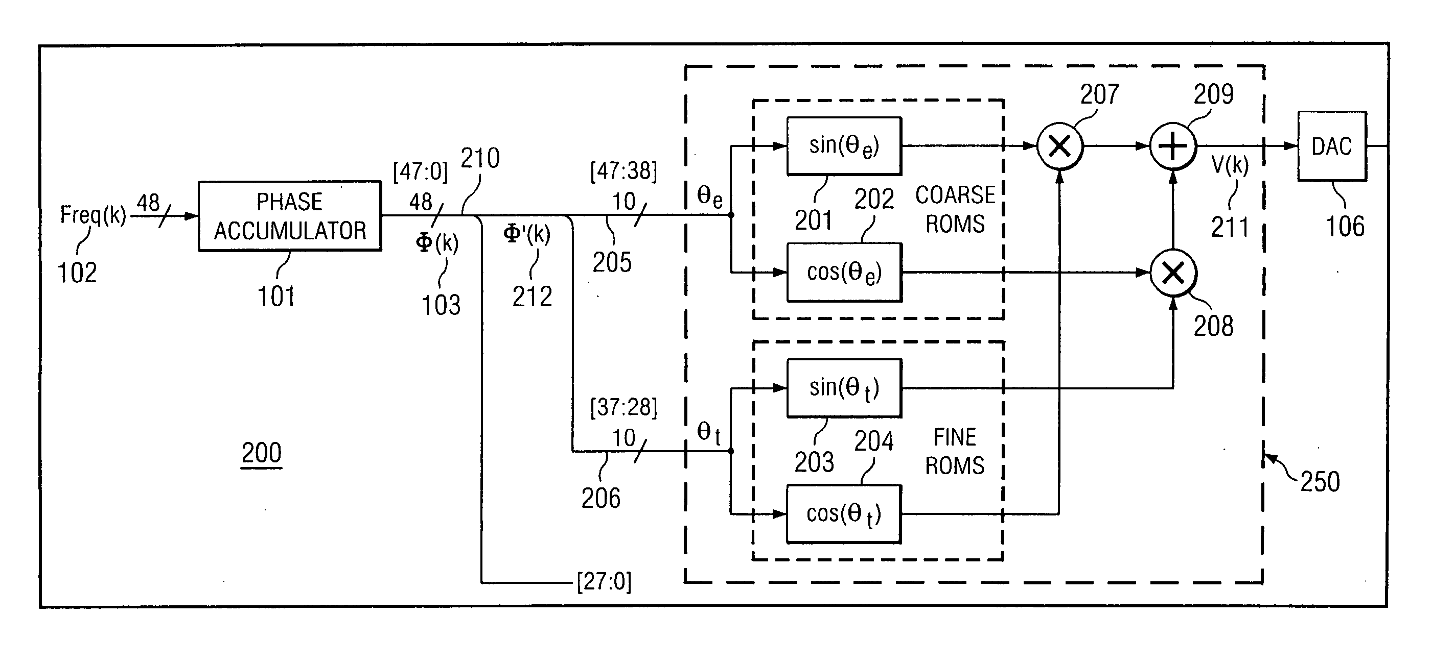
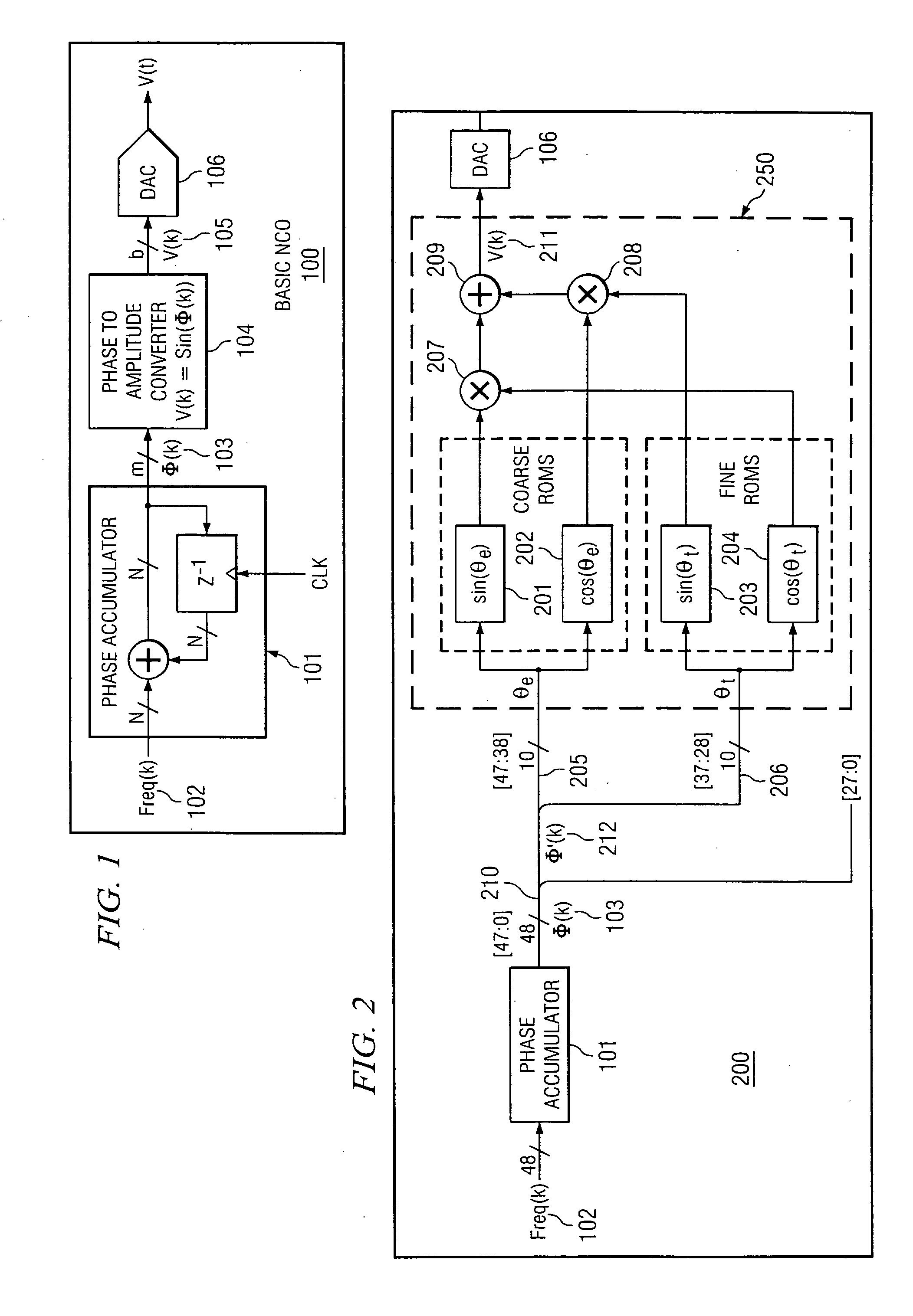
[0010] Referring now to one representative embodiment shown in FIG. 2, numerically controlled oscillator 200 receives input digital signal 102 (Freq(k)) to control the operating frequency of the oscillator. Input digital signal 102 is communicated using a bus having a bit width of 48-bits. Input digital signal 102 is accumulated by phase accumulator 101 to generate phase signal 103 (Φ(k)). Phase signal 103 is communicated on bus 210 that has a width of 48-bits.

[0011] As shown in FIG. 2, phase signal 103 is truncated. Specifically, the lines of bus 210 corresponding to bits [27:0] are terminated without connection to phase-to-amplitude converter 250. Truncated signal 212 (Φ′(k)) corresponds to bits [47:28]. The truncation occurs according to the desired level of accuracy associated with the subsequent phase-to-amplitude conversion. In an alternative embodiment, all of the bits from phase accumulator 101 could be used for the phase-to-amplitude conversion. As will be discussed in gre...


PUM


Abstract

In one embodiment, the present invention is directed to a numerically controlled oscillator. The numerically controlled oscillator comprises: a phase accumulator for receiving an input digital word; and a phase to amplitude converter that is operatively coupled to the phase accumulator to receive a first phase signal and a second phase signal, the phase to amplitude converter calculating a sine value and a cosine value of each of the first and second phase signals, the phase to amplitude converter generating a summation of (i) a product of the sine value of the first phase signal and the cosine value of the second phase signal and (ii) a product of the sine value of the second phase signal and the cosine value of the first phase signal.

Description

FIELD OF THE INVENTION [0001] The present invention is related to a numerically controlled oscillator. DESCRIPTION OF RELATED ART [0002] A numerically (or digitally) controlled oscillator is an electronic system for synthesizing a range of frequencies in response to a digital signal. The range of frequencies generated by a numerically controlled oscillator is related to the bit resolution of the input digital signal and the clock used to control the numerically controlled oscillator. In particular, the generated frequencies are less than half of the frequency of the clock used to control the numerically controlled oscillator as a result of Nyquist's theorem. [0003]FIG. 1 depicts numerically controlled oscillator 100 that is controlled by N-bit frequency word 102 (Freq(k)). Specifically, frequency word 102 defines the desired operating frequency of numerically controlled oscillator 100. Frequency word 102 is applied to phase accumulator 101 that is controlled by a clock to define the...

Claims


Application Information

Patent Timeline
Patent Type & Authority Applications(United States)
IPC IPC(8): G06F1/02G06F1/03G06F1/035
CPCG06F1/0353G06F1/0342
Inventor MILLER, BRIAN M.
Owner AGILENT TECH INC
Why Eureka
Try Eureka